AUTOMATION P R O D U C T S G R O U P, I N C. Operator’s Manual DCU-1104 and DCU-1108 Rev. A2, 11/06 Doc. 9002660 Automation Products Group, Inc. APG...Providing tailored solutions for measurement applications Tel: 1/888/525-7300 • Fax: 1/435/753-7490 • www.apgsensors.com • E-mail: sales@apgsensors.
DCU-1104 and DCU-1108 Rev. A2, 11/06 Table of Contents Warranty ......................................................................................... 3 Introducing ...................................................................................... 4 Understanding Ultrasonics ............................................................. 5 Installation ...................................................................................... 7 Wiring .....................................................
Rev. A2, 11/06 DCU-1104 and DCU-1108 • Warranty and Warranty Restrictions APG warrants its products to be free from defects of material and workmanship and will, without charge, replace or repair any equipment found defective upon inspection at its factory, provided the equipment has been returned, transportation prepaid, within 24 months from date of shipment from factory.
DCU-1104 and DCU-1108 Rev. A2, 11/06 • Introducing Thank you for purchasing the DCU-11 Programmable Ultrasonic Sensor. These sensors combine a versatile range of features to handle even the toughest measuring challenges in tank and environmental monitoring and control.
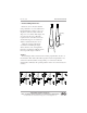
Rev. A2, 11/06 DCU-1104 and DCU-1108 • Understanding Ultrasonics Ultrasonic sensors measure distance using a transducer to send out ultrasonic bursts. Each burst contains a series of 120 pulsed sound waves that emit in the shape of a cone, reflect off the target, and are received by the sensor. The time required for the sound burst to travel to and from the target is converted into a distance measurement by the sensor.
DCU-1104 and DCU-1108 Rev. A2, 11/06 Distance The shorter the distance from the sensor to an object, the stronger the returning echo will be. Therefore, as the distance increases, the object requires better reflective characteristics to return a sufficient echo. Size A large object will have a greater surface area to reflect the signal than a small one, therefore, a large target will be detected at a greater distance than a small target.
Rev. A2, 11/06 DCU-1104 and DCU-1108 • Installation 1. Installation, use and maintenance shall be in accordance with the manufacturer’s instructions, the National Electrical Code and any applicable local codes. 2. Electrical equipment connected to associated apparatus should not use or generate more than 250Vrms. 3. Tampering or replacement with nonfactory components may adversely affect the safe use of the system. Automation Products Group, Inc. APG...
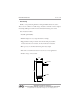
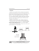
DCU-1104 and DCU-1108 Rev. A2, 11/06 • Installation The DCU-11 sensor should be mounted so that it has a clear sound path to the level monitored. Mount the sensor away from tank walls and inlets. The path should be free from obstructions and as open as possible for the 18° beam pattern (9° off axis). Follow the guidelines mentioned in "Understanding Ultrasonics", earlier in this manual. When using a stand pipe to mount the sensor above the tank, the stand pipe should be seamless and no longer than 4 in.
Rev. A2, 11/06 DCU-1104 and DCU-1108 • Wiring RED ................... 10 - 30 VDC (24 VDC recommended) BLACK .............. POWER SUPPLY GROUND YELLOW ........... ANALOG GROUND ORANGE ........... 4-20 mA ANALOG OUTPUT BLUE ................. RELAY 1 COMMON GRAY ................ RELAY 1 NORMALLY OPEN PURPLE ............ RELAY 2 COMMON BROWN ............. RELAY 2 NORMALLY OPEN GREEN .............. CLOCK SYNCHRONIZATION WHITE ............... DIGITAL OUT SHIELD .............
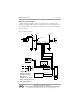
DCU-1104 and DCU-1108 Rev. A2, 11/06 Wiring for a Relay Output When switching a highly capacitive or inductive load, a swamping diode should be used. This will protect the internal relay from possible damage and prevent electrical noise from being introduced to the sensor which could result in false readings. DCU-11 Wiring Diagram A.C. 24VDC 24VDC 24 V DC COIL RELAY Swamping Diode Alarm Brown (N.O.) Purple (Common) Gray (N.O.) Blue (Common) Power Supply ACC-1008 24VDC Neg.
Rev. A2, 11/06 DCU-1104 and DCU-1108 • Programming The DCU-11 display and control buttons can be accessed by unscrewing the sealed cap on the rear of the sensor. The membrane display has two lights indicating the status of Trip Points 1 and 2. The LED display shows distance measurements. The display is also used when programming to display the individual modes and their values. The DCU-11 has four programming buttons, VALUE UP, VALUE DOWN, MODE UP and MODE DOWN.
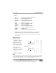
DCU-1104 and DCU-1108 Rev. A2, 11/06 Operation MODE 1 DESCRIPTION Units PARAMETERS Range = 1-3 1- inches 2- feet 3- meters The first thing to set up on the DCU-11 is the Units to be Displayed. The Units Mode is used to select the type of measurement and setup units in which you will operate. The units will also determine the resolution of the display and the outputs. The resolution is: inches .1, feet .01, and meters .01. NOTE: All modes must be set using the units in Mode 1.
Rev. A2, 11/06 DCU-1104 and DCU-1108 the Units (Mode 1) have been set. The blanking distance can also be used to ignore unwanted targets close to the sensor such as welds, seams, pipe fittings, or gaskets. MODE 4 DESCRIPTION Pulses PARAMETERS Units = 42 Khz soundwaves Range = 1-20 Default = 20 The Pulses mode controls how many pulsed soundwaves are transmitted in each ultrasonic burst. The DCU-11 sends out a transmission burst of pulses and measures the time it takes for the echo to return.
DCU-1104 and DCU-1108 MODE 7 DESCRIPTION Out-of-Range Samples MODE 8 DESCRIPTION Out-of-Range Span MODE 9 DESCRIPTION Loss of Echo Delay Rev. A2, 11/06 PARAMETERS Units = Samples Range = 1-200 Default = 5 This mode is used in conjunction with Out-of Range Span (Mode 8) to set an effective window for valid readings.
Rev. A2, 11/06 DCU-1104 and DCU-1108 Outputs Relay The two relays are fully programmable for BEGIN and END points and their Type of operation. The LEDs on the DCU-11 display labeled TRIP 1 and TRIP 2 indicate the status of the normally open relay contacts. When the LED is on, the relay is energized and the contact is closed. All distance settings will be in the UNITS selected in Mode 1. The relays are rated for 200 mA @ 24 VDC. Switching A.C. through the relay is not recommended.
DCU-1104 and DCU-1108 MODE 13 DESCRIPTION Begin Trip 2 MODE 14 DESCRIPTION End Trip 2 MODE 15 DESCRIPTION Trip 2 Type Rev. A2, 11/06 PARAMETERS Units = Mode 1 Range = 0 - 9999 Default = 3.50 Sets the Begin point for Trip 2 Relay Output. PARAMETERS Units = Mode 1 Range = 0 - 9999 Default = 4.50 Sets the End point for Trip 2 Relay Output.
Rev. A2, 11/06 DCU-1104 and DCU-1108 Trip Type Explanation Automation Products Group, Inc. APG...Providing tailored solutions for measurement applications Tel: 1/888/525-7300 • Fax: 1/435/753-7490 • www.apgsensors.com • sales@apgsensors.
DCU-1104 and DCU-1108 Rev. A2, 11/06 Analog The 4-20 mA analog output can be configured anywhere over the range of the DCU-11. The 4 mA end point is entered in mode 16 and the 20 mA end point in mode 17. The 4 and 20 mA values are calibrated at the factory but can be fine tuned by Modes 18 and 19. The DCU-11 will digitally create a straight line between the two points for the analog output. The resolution of the output will be the same as the displayed resolution.
Rev. A2, 11/06 DCU-1104 and DCU-1108 Calibration For most open air applications, the factory-set calibration should be correct. Variations between the distance measured by the DCU-11 and the actual distance are caused by environmental conditions such as temperature, humidity, or chemical atmosphere. These environments can be compensated for by using a calibration factor which calibrates the reading to match the actual distance.
DCU-1104 and DCU-1108 Rev. A2, 11/06 to be in the far left position. So a value of 53 would correspond to 0.0053, whereas 5300 would correspond to 0.5300.) EXAMPLE: The Calibration Factor is used to bring the displayed reading in line with the measured distance. To obtain the measured distance, measure from the target to be detected to .5 in. behind the DCU-11 face. (.5 in. behind the DCU-11 face is the electrical zero point of the sensor.
Rev. A2, 11/06 DCU-1104 and DCU-1108 Utilities Temperature Compensation As air temperature changes, so does the speed of sound. This change can cause 0.1% drift in distance for every °F change. Mode 24 allows compensation for this change. The DCU-11 contains an internal thermistor which measures temperature. By turning temperature compensation ON, the effects of temperature changes may be reduced by 50% or better.
DCU-1104 and DCU-1108 Rev. A2, 11/06 Software MODE DESCRIPTION 26 Software Version Mode 26 displays the software version for the DCU-11. The value corresponds to the operating version and the approximate date of manufacture. MODE 27 DESCRIPTION Autosense PARAMETERS Range = 0-1 0 = Manual (user controls Sensitivity and Pulses) 1 = Autosense (sensor controls Sensitivity and Pulses) Autosense mode sets control of the sensitivity and pulses to the sensor.
Rev. A2, 11/06 DCU-1104 and DCU-1108 Lift Station Example A 20 ft. deep lift station requires that a pump turn ON when a level is closer than 4 ft. to the DCU-11. The pump must stay on until the level drops to 18 ft. from the DCU-11. An alarm relay is to be energized under normal operation and should open for failure in power, communication, invalid readings, high level above 3 ft. from sensor, or loss of echo. Setting the averaging in Mode 6 at 10 to 20 samples will give a good stable reading.
DCU-1104 and DCU-1108 Rev. A2, 11/06 under the sensor. With the correct settings in Modes 7 and 8 the sensor will ignore the agitator when it passes in front of the sensor and stay locked on the level of the product in the tank. However, if the agitator stops directly below the sensor for a long period of time, eventually the number of Out-of-Range samples in Mode 7 will be exceeded and the sensor could start displaying the top of the agitator.
Rev. A2, 11/06 DCU-1104 and DCU-1108 • Mode Sheet MODE DESCRIPTION PARAMETERS EXPLANATION 1 Units Range = 1 - 3 1 - inches 2 - feet 3 - meters Default = 2 Select the units to be displayed and used in setup. NOTE: * Set Mode 1 first before any other modes. 2 Sensitivity Units = % Range = 0000-9999 FOR VIEWING ONLY. The first two digits display highest operating sensitivity and the last two digits display current sensitivity level. 3 Blanking Units = Mode 1 Range = 2.0 to 50 ft. Default = 2.
DCU-1104 and DCU-1108 Rev. A2, 11/06 • Mode Sheet (continued) MODE DESCRIPTION PARAMETERS EXPLANATION 9 Loss of Echo Delay Units = seconds Range=0-9999 Default = 5 Set the delay in seconds before the output will show a loss of echo condition. 10 Trip 1 Begin Units = Mode 1 Range = 0 - 9999 Default = 3.00 Sets the BEGIN point for Trip 1 Relay output. 11 Trip 1 End Units = Mode 1 Range = 0 - 9999 Default = 4.00 Sets the END point for Trip 1 Relay output.
Rev. A2, 11/06 DCU-1104 and DCU-1108 • Mode Sheet (continued) MODE DESCRIPTION PARAMETERS EXPLANATION 15 Trip 2 Type Range = 0 - 7 0 - near 1 - exclusive 2 - hysteresis near 3 - far 4 - inclusive 5 - hysteresis far 6 - disable 7 - loss of echo Default = 0 Selects the output type for Trip 2. 16 4mA* Units = Mode 1 Range = 0 - 9999 Default = 3.00 Sets the end point for the 4 mA analog limit. 17 20mA* Units = Mode 1 Range = 0 - 9999 Default = 4.00 Sets the end point for the 20 mA analog limit.
DCU-1104 and DCU-1108 Rev. A2, 11/06 • Mode Sheet (continued) MODE DESCRIPTION PARAMETERS EXPLANATION 24 Temperature Compensation Range = On/Off view Selects internal temperature compensation for changes in the Default = Off speed of sound caused by changing temperatures. On, Off, or View sensor temperature. 25 Reset Range = No/Yes Default = No 26 Software Version 27 AutoSense 28 Password Resets the mode parameters to their default values.
Rev. A2, 11/06 DCU-1104 and DCU-1108 • Hazardous Mounting Automation Products Group, Inc. APG...Providing tailored solutions for measurement applications Tel: 1/888/525-7300 • Fax: 1/435/753-7490 • www.apgsensors.com • sales@apgsensors.
DCU-1104 and DCU-1108 Rev. A2, 11/06 • Specifications — DCU-1104, DCU-1108 Operating Range .............. 2 ft. to 50 ft. (0.6 m - 15.24 m) Supply Voltage ................. 12 to 30 VDC (24 VDC recommended for maximum performance) Outputs ............................ • 4-20 mA • 2 solid state relays (130 mA max) Resolution ....................... 0.1 in. (2.54 mm) Accuracy ......................... 0.25% of range with no temp gradient Sensor Adjustments ........ programmable modes Total Current Draw .....
Rev. A2, 11/06 DCU-1104 and DCU-1108 Notes Automation Products Group, Inc. APG...Providing tailored solutions for measurement applications Tel: 1/888/525-7300 • Fax: 1/435/753-7490 • www.apgsensors.com • sales@apgsensors.
AUTOMATION P R O D U C T S G R O U P, I N C. APG...Providing tailored solutions for measurement applications Automation Products Group, Inc. Tel: 1/888/525-7300 1/435/753-7300 Fax: 1/435/753-7490 e-mail: sales@apgsensors.com www.apgsensors.com Automation Products Group, Inc. 1025 W. 1700 N.