AUTOMATION P R O D U C T S G R O U P, I N C. Operator’s Manual DCR-WEB Rev. A3, 10/08 Doc. 9002666 Automation Products Group, Inc. APG...Providing tailored solutions for measurement applications Tel: 1/888/525-7300 • Fax: 1/435/753-7490 • www.apgsensors.com • E-mail: sales@apgsensors.
DCR-WEB Rev. A3, 10/08 Table of Contents Warranty ......................................................................................... 3 Introducing ...................................................................................... 4 Understanding Ultrasonics ............................................................. 5 Installation ...................................................................................... 7 Wiring ...................................................................
Rev. A3, 10/08 DCR-WEB • Warranty and Warranty Restrictions APG warrants its products to be free from defects of material and workmanship and will, without charge, replace or repair any equipment found defective upon inspection at its factory, provided the equipment has been returned, transportation prepaid, within 24 months from date of shipment from factory.
DCR-WEB Rev. A3, 10/08 • Introducing The DCR-WEB is a non-contact loop control system that is shipped ready to be put into service. It has been completely tested at the factory and is easily configured to any application. The sensor is fully programmable to meet the needs of all different kinds of loop control applications. Operating parameters are modified using 4 push buttons and a 2 X 8 alphanumeric display. The controls are accessed by removing the front cover.
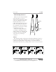
Rev. A3, 10/08 DCR-WEB • Understanding Ultrasonics Ultrasonic sensors measure distance using a transducer to send out ultrasonic bursts. Each burst contains a series of 1-20 pulsed sound waves that emit in the shape of a cone, reflect off the target, and are received by the sensor. The time required for the sound burst to travel to and from the target is converted into a distance measurement by the sensor.
DCR-WEB Rev. A3, 10/08 accuracy. Distance The shorter the distance from the sensor to an object, the stronger the returning echo will be. Therefore, as the distance increases, the object requires better reflective characteristics to return a sufficient echo. Size A large object will have a greater surface area to reflect the signal than a small one, therefore, a large target will be detected at a greater distance than a small target.
Rev. A3, 10/08 DCR-WEB • Installation Accurate readings require a clear sound path to the intended target. The path should be free from obstructions and as open as possible. Follow the guidelines mentioned in “Understanding Ultrasonics”. The DCR-WEB should be installed using the 4 screws through 4 holes in the bottom of the enclosure. Inputs • 110 VAC Power • 4 button Key Pad Mode Up, Mode Down, Number Up and Number Down Keys.
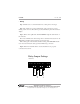
DCR-WEB Rev. A3, 10/08 • Wiring Step 1: Mount sensor so that transducer has a clear path to the target. Step 2: To obtain access to the terminal strip, remove the front cover by turning out the 4 screws. This will expose the terminal strip and 2 X 8 character display. Step 3: Wires can be pulled into the DCR-WEB through the strain reliefs on the enclosure. The screw terminal can be wired using solid or stranded wire between 16 - 20 AWG. Wires should be stripped, leaving a 0.4 in. bare wire.
Rev. A3, 10/08 DCR-WEB • Programming The DCR-WEB has a two line by eight character alphanumeric display. Four momentary push-buttons located under the cover, are used to program the sensor. The cover prevents the buttons from being accidentally bumped. The different modes can be easily accessed using the mode buttons, M-UP and M-DN. They operate similar to a digital watch. To cycle forward through the modes, hold down the M-UP key. To cycle backward through the modes, hold down the M-DN key.
DCR-WEB Rev. A3, 10/08 • Programming Modes For ease of programming, the DCR-WEB modes are grouped into phases of an application setup. The phases are: 1) 2) 3) 4) 5) Operation Filtering Outputs Calibration Utilities This order should be followed for setting up any application. Operation The operation modes are used to perform basic initialization of the DCR-WEB.
Rev. A3, 10/08 DCR-WEB Filtering The filtering modes are provided to change how fast the system will respond to changes. The default settings should be appropriate for most level applications, however, the delays and windows can be changed to increase or decrease reaction time and filtering. MODE DESCRIPTION PARAMETERS EXPLANATION SAMP RAT Sample Rate Units = milliseconds Sets the delay between sensor samples.
DCR-WEB Rev. A3, 10/08 Example: Ignoring Intermittent Noise The transceiver in the DCR-WEB is tuned to detect sound waves within a range. There are certain external sources of noise in that range that can affect the proper operation of the sensor, high pressure air escaping is the most common source. In order to have the sensor ignore this noise a filter has been installed. It allows the operator to set a threshold of the number of target that can be received.
Rev. A3, 10/08 DCR-WEB Outputs The DCR-WEB contains 2 relays which are capable of handling a 5 A load. These relays have programmable BEGIN and END points as well as TYPE of operation. The relays can also be jumpered NO (default) or NC. *see drawing on earlier page of this manual. MODE BEGRLY 1 DESCRIPTION PARAMETERS EXPLANATION Begin Trip 1 Units = inches Sets the begin point Default = 24 of Trip 1. • Straight line from inlet of press to reel or straightener exit point.
DCR-WEB Rev. A3, 10/08 Trip Type Explanation Automation Products Group, Inc. APG...Providing tailored solutions for measurement applications 14 Tel: 1/888/525-7300 • Fax: 1/435/753-7490 • www.apgsensors.com • sales@apgsensors.
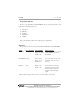
Rev. A3, 10/08 DCR-WEB Example: Relay Settings For High and Low Level Indication With the sensor mounted at 52.5 in. off of the floor looking down. An indication is needed if the material being monitored is detected closer than 13 in. or lower than 39 in. from the sensor. Relay number 1 will be used to activate an alarm. To program the DCR-WEB for this application, the following modes must be set: MODE BEGRLY 1 ENDRLY 2 TYPE 1 VALUE 13.0 39.
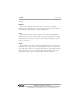
DCR-WEB Rev. A3, 10/08 Calibration Analog The DCR-WEB has an Isolated 0-10 V output. To set up this feature, enter the two end points. If the level is beyond the bounds of the window created by the two end points the voltage level will stay at the voltage level of the point it is nearest to. Refer to the diagram below. 10 VDC 10 VDC 0 VDC 0 VDC Zero Point MODE 0V DIST 10 V 0 V Distance Distance DESCRIPTION 0 V Distance 10V DIST 10 V Distance Max.
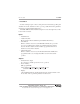
Rev. A3, 10/08 DCR-WEB Utilities Temperature Compensation As air temperature changes, so does the speed of sound. This change can cause 0.18% drift in distance for every °C change. The TEMPCOMP Mode allows compensation in the readings for this change. The DCR-WEB contains an internal thermistor which measures temperature in °F. By turning temperature compensation on, the effects of temperature changes will be reduced.
DCR-WEB Rev. A3, 10/08 The Calibration parameter is used to adjust the unit for the change in speed of sound due to environments other than air. For example, units operating in a heavy fuel or gaseous environment may wish to calibrate the controller output distance with a measured distance. For most applications, this parameter will remain at 1.000. MODE Calib DESCRIPTION Calibration PARAMETERS Range = 0.000 - 9.999 Default = 1.
Rev. A3, 10/08 DCR-WEB • Specifications Operating Range .............. 6 in. to 120 in. Sample Rate ..................... 40 to 120 msec Outputs ............................ Isolated 0 to 10 VDC 2 relays (5 A 120 VAC) Enclosure ......................... Poly-Carbonate Transducer Type .............. Electrostatic/Ceramic Ratings ............................. NEMA 4 Operating Temperature .... -20 to 140°F Internal Temperature Compensation .................. yes Accuracy .......................... ± 0.
DCR-WEB Rev. A3, 10/08 • Maintenance The DCR-WEB sensor does not require maintenance. However, a periodic visual inspection of the system would be in order. The transducer should be kept as clean as possible for optimum performance. Dust buildup may be removed from the transducer with a cloth or by low pressure air. Automation Products Group, Inc. APG...Providing tailored solutions for measurement applications 20 Tel: 1/888/525-7300 • Fax: 1/435/753-7490 • www.apgsensors.com • sales@apgsensors.
Rev. A1, 10/08 DCR-WEB Notes Automation Products Group, Inc. APG...Providing tailored solutions for measurement applications Tel: 1/888/525-7300 • Fax: 1/435/753-7490 • www.apgsensors.com • sales@apgsensors.
DCR-WEB Rev. A3, 10/08 Notes Automation Products Group, Inc. APG...Providing tailored solutions for measurement applications 22 Tel: 1/888/525-7300 • Fax: 1/435/753-7490 • www.apgsensors.com • sales@apgsensors.
Rev. A1, 10/08 DCR-WEB Notes Automation Products Group, Inc. APG...Providing tailored solutions for measurement applications Tel: 1/888/525-7300 • Fax: 1/435/753-7490 • www.apgsensors.com • sales@apgsensors.
AUTOMATION P R O D U C T S G R O U P, I N C. APG...Providing tailored solutions for measurement applications Automation Products Group, Inc. Tel: 1/888/525-7300 1/435/753-7300 Fax: 1/435/753-7490 e-mail: sales@apgsensors.com www.apgsensors.com Automation Products Group, Inc. 1025 W. 1700 N.