
user manual Instruction Manual


Rev. A1, 2/14 DCR-1006A Ultrasonic Controller
11
Automaon Products Group, Inc.
APG...Providing tailored soluons for measurement applicaons
Tel: 1/888/525-7300 • Fax: 1/435/753-7490 • www.apgsensors.com • sales@apgsensors.com
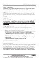
RST Module Wiring: connect the RS-485
NET A(-) and B(+) terminals to the A and B
terminals of the RST module.
Vs
A (-)
B(+)
A1 (-)
B1(+)
OUT
RST Module
RST-5002 or RST-6001 Communicaon Module Wiring
The DCR-1006A can be connected to the RST-6001 RS-485-to-USB module for
interfacing with the APG Modbus soware, or to the RST-5002 internet commu-
nicaons module to provides remote access to the DCR’s readings and sengs.
The “RS-485 NET A and B terminals are the only connecon required for either
RST module.
Wiring the Switched Input for High/Low Level Backup
The DCR’s Switched Input can be connected to simple switching device, such as
a oat switch, to provide a high/low level backup and prevent dry pumping or
overow condions in the event of an ultrasonic sensor failure or malfuncon.
IN
GND
N.O.
COM
N.C.
N.O.
COM
N.C.
N.C.
Switch
Relay Controlling
Pump/Valve
Switched
Input
Relay Controlled
by Switch Input
IN
GND
N.O.
COM
N.C.
N.O.
COM
N.C.
N.O.
Switch
Relay Controlling
Pump/Valve
Switched
Input
Relay Controlled
by Switch Input
Normally Open
Switched Input
Normally Closed
Switched Input