
user manual User Manual

Rev. A3, 10/08 DCR-1003 and DCR-1004
41
Automation Products Group, Inc.
APG...Providing tailored solutions for measurement applications
Tel: 1/888/525-7300 • Fax: 1/435/753-7490 • www.apgsensors.com • sales@apgsensors.com
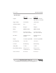
• Trouble Shooting
The DCR-1003, DCR-1004 and DST sensor are a rugged, reliable level
measurement system that is easy to install and setup. But occasionally problems
will occur during set up. A list of symptoms and possible corrective actions are
provided for troubleshooting.
SYMPTOM CAUSE ACTION
DISTANCE DISPLAY ON Short circuit • Verify coaxial connections
COM. LED IS OFF on the transducer and wiring on cable or connector
• Sensor failure
COM. LED FLASHING Communication • Check coaxial cable and
EVERY .5 SECONDS error connectors for tight connection
• Sensor failure in communication
circuit
COM. LED FLASHING Loss of echo • Poor target characteristics see
EVERY SECOND “understanding ultrasonics”
section
• Sensor failure in transducer circuit
DISPLAY READS ---- Display overflow • Change calibration, multiplier, or
decimal point position
• DST & DCR are incompatible,
upgrade DST software
DISPLAY WILL NOT Sensor is seeing the • Remove detected object at
CHANGE BUT LEVEL wrong target measured distance
DOES • Mount the sensor away from tank
seams or obstructions
DISPLAY WILL ONLY Sensor is receiving • Check transducer installation for
READ AT CLOSE strong echoes in its smooth sound propagation into
DISTANCE blanking distance tank or to desired target
• Increase blanking distance mode 2