
user manual User Manual

Rev. A3, 10/08 DCR-1003 and DCR-1004
37
Automation Products Group, Inc.
APG...Providing tailored solutions for measurement applications
Tel: 1/888/525-7300 • Fax: 1/435/753-7490 • www.apgsensors.com • sales@apgsensors.com
Calibration
For most open air applications, the factory-set calibration should be correct.
Variations between the distance measured by the DCR/DST System and the
actual distance are caused by environmental conditions such as temperature,
humidity, or chemical atmospheres. These environments can be compensated
for by using a calibration factor which alters the reading to match the
application conditions.
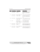
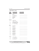
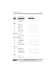
MODE DESCRIPTION PARAMETERS EXPLANATION
45 Distance Offset Units = mode 1 Sets an offset for the display
Range = 0.000 - 9999 when measuring distance to a
Default = 0 level
46 Offset Polarity Range = NEG, POS Selects the direction of the
Default = NEG offset, adds or subtracts offset to
reading, set by NUM UP or
NUM DN
47 Calibration Range = 0 - 9999 Sets the integer portion of the
Above the Default = 1 calibration factor
Decimal Point
48 Calibration Range = .0000 - .9999 Sets the fractional portion of the
Below the Default = 0 calibration factor
Decimal Point
Example 11: Calibration
1 Point Calibration
The Calibration Factor is used to bring the displayed reading in line with the
measured distance. To obtain the measured distance, measure from the level to
be detected to .5 in. behind the DST face. (.5 in. behind the DST face is the
electrical zero of the sensor.) The calibration factor is determined by dividing
the actual distance measured, by the displayed distance. Enter this number in
the calibration modes 45 and 46.
2 Point Calibration
If a more precise calibration is required, a two point calibration should be
used. This is accomplished by using the linear equation of Y = AX + B where;