AUTOMATION P R O D U C T S G R O U P, I N C. Operator’s Manual DCR-1003 and DCR-1004 Rev. A3, 10/08 Doc. 9002661 Automation Products Group, Inc. APG...Providing tailored solutions for measurement applications Tel: 1/888/525-7300 • Fax: 1/435/753-7490 • www.apgsensors.com • E-mail: sales@apgsensors.
DCR-1003 and DCR-1004 Rev. A3, 10/08 Table of Contents Warranty ......................................................................................... 3 Introducing ...................................................................................... 4 Understanding Ultrasonics ............................................................. 5 Installation ...................................................................................... 7 Installing the DST Sensor ..................................
Rev. A3, 10/08 DCR-1003 and DCR-1004 • Warranty and Warranty Restrictions APG warrants its products to be free from defects of material and workmanship and will, without charge, replace or repair any equipment found defective upon inspection at its factory, provided the equipment has been returned, transportation prepaid, within 24 months from date of shipment from factory.
DCR-1003 and DCR-1004 Rev. A3, 10/08 • Introducing The DCR-1003, 1004 controllers with DST series sensors were specifically designed to provide a rugged and reliable non-contact sensor system that is easily programmed yet flexible enough to use in a wide range of applications. The DCR-1003, 1004 controllers have a large display to show readings and parameters. They also include a mode display to provide easy setup of the programmable modes.
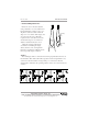
Rev. A3, 10/08 DCR-1003 and DCR-1004 • Understanding Ultrasonics Ultrasonic sensors measure distance using a transducer to send out ultrasonic bursts. Each burst contains a series of 120 pulsed sound waves that emit in the shape of a cone, reflect off the target, and are received by the sensor. The time required for the sound burst to travel to and from the target is converted into a distance measurement by the sensor.
DCR-1003 and DCR-1004 Rev. A3, 10/08 Distance The shorter the distance from the sensor to an object, the stronger the returning echo will be. Therefore, as the distance increases, the object requires better reflective characteristics to return a sufficient echo. Size A large object will have a greater surface area to reflect the signal than a small one, therefore, a large target will be detected at a greater distance than a small target.
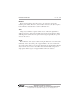
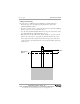
Rev. A3, 10/08 DCR-1003 and DCR-1004 • Installation Installing the DST Sensor The DST sensor should be installed so that it has a clear sound path to the intended target. The path should be free from obstructions and as open as possible. Follow the guidelines mentioned in this manual under “Understanding Ultrasonics”, found on page 5. NPT and Flange Mounting • Mounting in a coupler or half coupler welded to the top of tank. (see drawings below) • Coupling should extend through the top of tank.
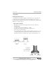
DCR-1003 and DCR-1004 Rev. A3, 10/08 Stand Pipe Mounting The stand pipe should be as large in diameter and as short in length as possible. Mount the sensor above the highest anticipated material by at least the published blanking distance. The stand pipe should be seamless to provide a smooth path for the sound waves to propagate into the tank.
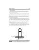
Rev. A3, 10/08 DCR-1003 and DCR-1004 Stilling Well Mounting Provides access to difficult areas and eliminates problems with foam. • Extend the pipe above the highest anticipated level by at least the published blanking distance. • Provide a vent hole at the top of the tube. Keep the hole inside the blanking distance of the sensor to prevent false echoes. • Use only in liquid materials that will not leave deposits on the inside of the pipe (material build-up will result in false echoes).
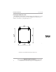
DCR-1003 and DCR-1004 Rev. A3, 10/08 Installing the DCR-1003, 1004 The DCR-1003, 1004 should be installed using the 4 mounting feet provided. The enclosure must be mounted out of direct sunlight and should have good clearance to the left for opening the hinged cover. DCR-1003 and DCR-1004 Mounting Dimensions Automation Products Group, Inc. APG...Providing tailored solutions for measurement applications 10 Tel: 1/888/525-7300 • Fax: 1/435/753-7490 • www.apgsensors.com • sales@apgsensors.
Rev. A3, 10/08 DCR-1003 and DCR-1004 • Wiring Step 1: Connect the DST to the DCR Controller using RG-6 coaxial cable with ‘F’ series connectors. If more than one DST is to be connected for a differential application, the two sensors should be connected to the DCR using an external splitter. Step 2: To obtain access to the DCR’S terminal strip, open the DCR’s plexiglass cover and raise the hinged panel by loosening the knurled thumb screws.
DCR-1003 and DCR-1004 Rev. A3, 10/08 Step 4: Wires can be pulled into the DCR-1003, 1004 through the strain reliefs on the enclosure, or the strain reliefs may be removed and 1/2 in. conduit used in their place. The spring loaded terminal can be wired using solid or stranded wire between 16 - 20 AWG. Wires should be stripped, leaving a .4 in. bare wire. The wires can then be inserted into the terminal by depressing the associated orange lever with a #5 1/8 in. screwdriver.
Rev. A3, 10/08 DCR-1003 and DCR-1004 • Programming The DCR-1003, 1004 has a four-digit LED readout, a two-digit display showing the modes, and four lights labeled TRIPS 1, 2, 3, and 4. These lights indicate the status of the relays. The keypad, located under the clear cover, is used to program the DCR-1003, 1004. The front cover makes reading the displays easy while preventing the buttons on the keypad from being accidentally bumped.
DCR-1003 and DCR-1004 Rev. A3, 10/08 Mode Sequence For best results when programming your DCR, follow the steps below. Following the steps in sequence will eliminate most of the problems encountered when setting up the DCR controller. 1. MODES 1-2 Determine units to be displayed 2. MODES 4-6 Determine settings to get a reliable distance reading on your target 3. MODES 7-10 Determine appropriate filtering for your application 4.
Rev. A3, 10/08 DCR-1003 and DCR-1004 Operation The operation modes are used to do basic initialization of the DCR. MODE DESCRIPTION PARAMETERS 1 Units Range = 1 - 3 1 - inches 2 - feet 3 - meters Default = 2 EXPLANATION Selects the units to be displayed Select by NUM UP or NUM DN 2 Decimal Point Range = 0000.- 0.000 Default = 00.
DCR-1003 and DCR-1004 Rev. A3, 10/08 Filtering (Modes 7-9) The filtering modes are provided to adjust how fast the system will respond to target changes. The default settings should be appropriate for most level applications. However, the filtering can be changed to increase or decrease reaction time to keep up with fast moving targets and filter out unwanted targets. MODE DESCRIPTION PARAMETERS 7 Sample Rate Units = seconds Delay Range = 0.075 – 1.0 sec. Default = .
Rev. A3, 10/08 DCR-1003 and DCR-1004 distance reading. If a target is sampled outside of this window it will be ignored until it is consecutively sampled the number of times set in mode 9. When the sensor accepts a new target, the window automatically shifts to the new target. 11 Loss of Echo Units = seconds Range = 0 - 9999 Default = 5 Sets the delay before the output will show a loss of echo condition. A loss of echo condition exists when the sensor looses all targets (receives no echo returns).
DCR-1003 and DCR-1004 Rev. A3, 10/08 MODE DESCRIPTION 7 Set the sample rate delay as high as is practical in your application to allow more time for the previous sound wave to dissipate before transmitting the next wave. This will minimize the chances of multiple-echo interference. 8 Set the samples averaged as high as is practical in your application to help minimize the effects of waves and ripples on a liquid target.
Rev. A3, 10/08 DCR-1003 and DCR-1004 Outputs The DCR-1003 comes standard with 4 relay outputs fused at 5 A each. The DCR-1004 is equipped with relays and an analog output. Detailed explanations of the two output types are given in the RELAY and ANALOG sections. RELAY The four relays are fully programmable for ‘BEGIN’ and ‘END’ points and ‘TYPE’ of operation. The LEDs on the DCR indicate the status of the normally open relays. When the LED is on, the relays are energized and the contact is closed.
DCR-1003 and DCR-1004 Rev. A3, 10/08 17 Trip 2 Type Range = 0 - 7 Default = 0 Selects the type of function function Trip 2 will perform 18 Begin Trip 3 Units = mode 1/mode 3 Sets the begin point Default = 3.50 ft. of Trip 3 19 End Trip 3 Units = mode 1/mode 3 Sets the end point Default = 3.90 ft. of Trip 3 20 Trip 3 Type Range = 0 - 7 Default = 0 21 Begin Trip 4 Units = mode 1/mode 3 Sets the begin point Default = 4.0 ft.
Rev. A3, 10/08 DCR-1003 and DCR-1004 Trip Type Explanation ZERO BEGIN END Type 0: Near On Off Off Type 1: Exclusive On Off On Off Off Type 2: Hysteresis Near On On Type 3: Far Off On On Type 4: Inclusive Off On Off On On Type 5: Hysteresis Far Type 6: Off Off Trip Point Disable Type 7: Relay remains closed (trip light on) unless an error is detected in communication, loss of echo, or loss of power.
DCR-1003 and DCR-1004 Rev. A3, 10/08 Example 3- Relay Settings for Distance to Level A 10 ft deep lift station requires that a pump turn on when a level is closer than 6 ft. to the DST. The pump must stay on until the level drops to 9 ft. from the DST. An alarm relay is to be energized under normal operation and should open for failure in power, 6 ft communication, invalid readings, 10 ft high level closer than 5 ft., or loss of echo.
Rev. A3, 10/08 DCR-1003 and DCR-1004 Example 4- Relay Settings For Product Level Rather than Distance to Level A 10 ft. deep lift station requires that a pump turn on when a level reaches 4 ft. and stay on until the level drops to 1 ft. from the bottom of the station. An alarm relay is to be energized under 6 ft normal operation and should open 9 ft for failure in power, 10 ft communication, invalid readings, high level above 5 ft., or loss of 4 ft echo.
DCR-1003 and DCR-1004 Rev. A3, 10/08 ANALOG The analog output is only available on controller model DCR-1004. The analog circuit comes standard with 4-20 mA, but may be configured for 0-20 mA. A hardware change will allow 0-5 V, or 0-10 V as the output. The desired analog output should first be selected in mode 24. The two end points must then be entered.
Rev. A3, 10/08 DCR-1003 and DCR-1004 Applications The DCR Controller can be configured for four different types of applications. They are: • Distance: Measuring the distance to an object • Volume: Determining the volume, or level of a product in a tank • Differential: Calculating the differential measurement between two levels or measurements • Open Channel Flow: Taking flow rate measurements over a weir or flume DISTANCE Measuring the distance to a target is the most basic application.
DCR-1003 and DCR-1004 Rev. A3, 10/08 VOLUME A very popular use for the DCR-1003, 1004 is to do volumetric conversions for the amount of product in a tank. If 0 is selected as the tank type , the zero point is at the DST, and the display will show the distance to the product. If tank type 1 - 5 are selected, the zero point is the bottom of the tank, and the display will show how much product is in the tank.
Rev. A3, 10/08 DCR-1003 and DCR-1004 Decimal Point Default = .0000 below the decimal point. 32 Span Units = mode 1 Default = 12.00 ft. Sets the empty distance from the transducer 33 Tank Length Units = mode 1 Default = 10.00 ft. Sets the length of a horizontal tank or the length to a conical bottom 34 Length of Spherical Ends Units = mode 1 Default = 2.00 ft. Sets the length of the bottom cone or spherical or Cone ends (tank type 3 or 5) 35 Tank Radius Units = mode 1 Default = 5.00 ft.
DCR-1003 and DCR-1004 Rev. A3, 10/08 Volume Example 1 Gallons of diesel fuel need to be displayed in the horizontal tank with spherical ends shown below. 1.2 ft. 6 ft. 5 ft. 3 ft. 10 ft. To program the DCR for this application will require the following steps: MODE 1 4-10 3 2 VALUE 2 --2 0000. 29 30 3 7 31 4805 32 6 33 34 35 12-26 10 1.2 2.5 --- DESCRIPTION Set the units to feet. Determine settings to achieve reliable reading of the target.
Rev. A3, 10/08 DCR-1003 and DCR-1004 Volume Example 2 Liters of water need to be displayed in the cylindrical flat bottom tank shown below. MODE 1 4-10 VALUE 2 --- 3 2 2 0000. 29 1 11 ft. 9 in. DESCRIPTION Set units to feet 6 ft. 9 in. Determine settings to achieve reliable reading of the target. Select volume as operating mode. Move the decimal 8 ft. point to the far right. The tank has a capacity of more than 15,000 liters.
DCR-1003 and DCR-1004 Rev. A3, 10/08 DIFFERENTIAL The DCR-1003, 1004 can determine the difference between two levels. This is accomplished by installing two DSTs at the same height, one over each level to be monitored. The DSTs are then programmed as different sensor numbers, # 1 and # 2. The DCR-Controller will take the two level readings and display the difference.
Rev. A3, 10/08 DCR-1003 and DCR-1004 Differential CONNECT ONLY ONE OF THE DST SENSORS TO THE DCR-1003, 1004 36 2 Program the DST that is connected to the DCR-Controller to be sensor # 2. The other DST will be sensor # 1 as set at the factory CONNECT BOTH DST SENSORS TO THE DCR- CONTROLLER BY USING THE COAXIAL SPLITTER (obtained from APG) 37 1 37 2 37 0 The display will show the distance from DST # 1 to the level.
DCR-1003 and DCR-1004 Rev. A3, 10/08 OPEN CHANNEL FLOW The DCR-1003, 1004 and DST ultrasonic system can be used to compute the flow of a liquid in an open channel such as rivers, canals, and partially filled conduits. The flow is determined by using the DCR/DST system to measure the liquid level upstream from a weir or flume. Weirs and flumes are simply special shaped dams or restrictors built in a channel. Each type of weir or flume has an associated equation for calculating flow.
Rev. A3, 10/08 MODE DESCRIPTION 38 Constant Above Decimal Point DCR-1003 and DCR-1004 PARAMETERS Range = 0 - 9999 Default = 1 EXPLANATION Sets the portion of the multiplier (K) above the decimal point, used for converting distance to flow 39 Constant Below Decimal Point Range = .0000 - .9999 Default = .0000 Sets the portion of the multiplier (K) below the decimal point, used for converting distance to flow 40 Decimal Point Range = 0000. - 0.000 Default = 00.
DCR-1003 and DCR-1004 Rev. A3, 10/08 Example 8: Weir The inlet flow to an irrigation reservoir is to be monitored and displayed in cubic feet per second (CFS). A 5 ft. rectangular weir without end contractions is to be used as the primary measuring device. The associated flow equation for the 5 ft. weir is: Flow in CFS = 16.65 * H^1.5 where H = the height of the pool above the weir crest By mounting the DST sensor more than 2.00 ft.
Rev. A3, 10/08 DCR-1003 and DCR-1004 Example 9: Flume A 1 meter wide cutthroat flume has been installed on the outlet of a water treatment plant. Flow is to be displayed in liters/sec. (LPS). The associated flow equation for the 1 meter flume is: Flow in LPS = 11.48 * H^1.56 where H is the upstream head measurement as specified for this flume type. To program the DCR-1003, 1004 for this application, the following modes must be set: MODE VALUE Operation 1 3 3 5 4 0.
DCR-1003 and DCR-1004 Rev. A3, 10/08 Temperature Compensation As air temperature changes, so does the speed of sound. This change can cause .18% drift in distance for every °C change. Mode 44 allows compensation in the readings for this change. The DST contains an internal thermistor which measures temperature in degrees F. By turning temperature compensation on, the effects of temperature changes may be reduced by 50%.
Rev. A3, 10/08 DCR-1003 and DCR-1004 Calibration For most open air applications, the factory-set calibration should be correct. Variations between the distance measured by the DCR/DST System and the actual distance are caused by environmental conditions such as temperature, humidity, or chemical atmospheres. These environments can be compensated for by using a calibration factor which alters the reading to match the application conditions.
DCR-1003 and DCR-1004 Y = measured distance A = Multiplier Rev. A3, 10/08 X = DCR Reading B = Offset The multiplier (A) can be determined by taking ultrasonic readings at two known distances and dividing the difference of the known distances (D) by the difference of the ultrasonic (U) readings (A) = (D2-D1)/ (U2-U1) where; D2 = far known distance U2 = Ultrasonic reading at D2 D1 = close known distance U1 = Ultrasonic reading at D1 Enter this multiplier in Modes 47 and 48.
Rev.
DCR-1003 and DCR-1004 MODE DESCRIPTION Rev. A3, 10/08 PARAMETERS Analog (continued) 27 0 or 4 mA Trim 28 20 mA Trim ________________________ ________________________ Volume 29 30 31 32 33 34 35 ________________________ ________________________ ________________________ ________________________ ________________________ ________________________ ________________________ Tank Type Mult Above Mult Below Span Tank Length Sphere.
Rev. A3, 10/08 DCR-1003 and DCR-1004 • Trouble Shooting The DCR-1003, DCR-1004 and DST sensor are a rugged, reliable level measurement system that is easy to install and setup. But occasionally problems will occur during set up. A list of symptoms and possible corrective actions are provided for troubleshooting. SYMPTOM CAUSE DISTANCE DISPLAY ON Short circuit COM. LED IS OFF on the transducer ACTION • Verify coaxial connections and wiring on cable or connector • Sensor failure COM. LED FLASHING EVERY .
DCR-1003 and DCR-1004 Rev. A3, 10/08 • Maintenance The DCR-1003, 1004 controller and DST sensor do not require maintenance. However, a periodic visual inspection of the system would be in order. The DST should be kept as clean as possible for optimum performance. Dust buildup may be removed from the transducer with a cloth or by low pressure air. The DST-PVC can be cleaned with soap and water. If the DST is visibly effected by the environment, a different type of transducer may be required.
Rev. A3, 10/08 DCR-1003 and DCR-1004 • Specifications Outputs DCR-1003 4 relays (5 A 110 VAC) DCR-1004 4 relays (5 A 110 VAC) with 4-20 mA or 0-20 mA Supply Voltage 110-220 VAC 110-220 VAC Total Current Draw 0.1 A 0.1 A Housing fiberglass fiberglass Rating NEMA 4X, IP65 NEMA 4X, IP65 Dimensions 8.5 x 6.5 x 4.25 in. (216 x 165 x 108 mm) 8.5 x 6.5 x 4.25 in. (216 x 165 x 108 mm) Resolution maximum of .01 in. (.25 mm) maximum of .01 in. (.
AUTOMATION P R O D U C T S G R O U P, I N C. APG...Providing tailored solutions for measurement applications Automation Products Group, Inc. Tel: 1/888/525-7300 1/435/753-7300 Fax: 1/435/753-7490 e-mail: sales@apgsensors.com www.apgsensors.com Automation Products Group, Inc. 1025 W. 1700 N.