
user manual Owner manual


Rev. A3, 10/08 AGV-1000
9
Automation Products Group, Inc.
APG...Providing tailored solutions for measurement applications
Tel: 1/888/525-7300 • Fax: 1/435/753-7490 • www.apgsensors.com • sales@apgsensors.com
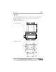
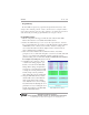
• Wiring (continued)
Attach Transducer #1 RED to FE1(+)
Attach Transducer #1 BLACK to T1(-)
Attach Transducer #1 Shield to GND
Attach Transducer #2 RED to FE2(+)
Attach Transducer #2 BLACK to T2(-)
Attach Transducer #2 Shield to GND
Attach Transducer #3 RED to FE3(+)
Attach Transducer #3 BLACK to T3(-)
Attach Transducer #3 Shield to GND
Attach Transducer #4 RED to FE4(+)
Attach Transducer #4 BLACK to T4(-)
Attach Transducer #4 Shield to GND
Attach Transducer #5 RED to FE5(+)
Attach Transducer #5 BLACK to T5(-)
Attach Transducer #5 Shield to GND
Attach Transducer #6 RED to FE6(+)
Attach Transducer #6 BLACK to T6(-)
Attach Transducer #6 Shield to GND
Attach Transducer #7 RED to FE?(+)
Attach Transducer #7 BLACK to T7(-)
Attach Transducer #7 Shield to GND
Attach Transducer #8 RED to FE?(+)
Attach Transducer #8 BLACK to T8(-)
Attach Transducer #8 Shield to GND
11
12 13 14
1 2 3 4 5 6 7 8 9 10
15 16 17 18 19 20 21 22 23 24 25 26 27 28
F
E
1
(
+
)
T
1
(
-
)
G
N
D
F
E
2
(
+
)
T
2
(
-
)
G
N
D
F
E
3
(
+
)
T
3
(
-
)
G
N
D
F
E
1
(
+
)
G
ND
F
E
2
(
+
)
T
7
(
-
)
F
E
3
(
+
)
G
ND
G
N
D
G
ND
G
N
D
F
E
4
(
+
)
T
4
(
-
)
F
E
5
(
+
)
T
5
(
-
)
F
E
6
(
+
)
T
6
(
-
)
F
E
4
(
+
)
F
E
5
(
+
)
F
E
6
(
+
)
T
8
(
-
)
1 2 3 4 5 6 7 8 9 10
11 12 13 14 15 16 17 18 19 20
V
(
+
)
G
ND
I
N
1
(
+
)
I
N
1
(
-
)
I
N
2
(
+
)
I
N
2
(
-
)
O
U
T
1
(
+
)
O
U
T
1
(
-
)
O
UT
2
(
+
)
O
U
T
2
(
-
)
V
(
+
)
G
N
D
I
N3
(
+
)
I
N
3
(
-
)
I
N4
(
+
)
I
N
4
(
-
)
O
U
T
3
(
+
)
O
UT
3
(
-
)
O
U
T
4
(
+
)
O
UT
4
(
-
)
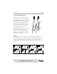
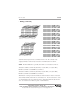
NOTE: The AGV-1000 can be optionally wired with 7 or 8 transducers as follows:
Transducer 7: RED to terminal 10 (share FE1); 11 (share FE2); or 14 (share FE3),
BLACK to terminal 12, and SHIELD to terminal 13.
Transducer 8: RED to terminal 24 (share FE4); 25 (share FE5); or 28 (share FE6),
BLACK to terminal 26, and SHIELD to terminal 27.
The limitation of using more than 6 transducers is that transducers 7 and/or 8 must each
share a FE (Front End) circuit with one of transducers 1-6. If a short circuit error occurs
on a shared FE, then the system will not be able to distinguish which transducer has the
error. As a result, the error will be reported on both transducers.
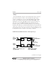
Attach the discrete input controls to terminals 3-6 and 13-16. The solid state relay
outputs (terminals 7-10 and 17-20) are rated for a maximum current of 130 mA.