
user manual Owner manual


AGV-1000 Rev. A3, 10/08
14
Automation Products Group, Inc.
APG...Providing tailored solutions for measurement applications
Tel: 1/888/525-7300 • Fax: 1/435/753-7490 • www.apgsensors.com • sales@apgsensors.com
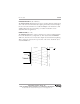
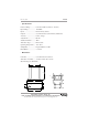
• Inputs
The AGV-1000 has four discrete inputs. Inputs 1 to 3 are used in combination
to select between different setups. Input 4 is used to select between LONG and
SHORT operating ranges. By changing the “on/off” combinations of inputs 1
to 3, we are able to get the 8 different input options below.
NOTE: Input 1 = least significant bit; Input 3 = most significant bit
INPUT 3 INPUT 2 INPUT 1 BINARY
Off Off Off 000
Off Off On 001
Off On Off 010
Off On On 011
On Off Off 100
On Off On 101
On On Off 110
On On On 111
On = Potential across IN(+) and IN(-)
Off = No potential across IN(+) and IN(-)
For each of the 8 input combinations, the user can set the following
parameters:
FRONT END ENABLE — (front-end circuit numbers 0 to 123456)
The Front End Enable parameters allow the user to define which of the six
front-end circuits are active for each of the 8 combinations of inputs 1-3. Each
front-end circuit controls a corresponding transducer. Assigning active front-
end circuits is as simple as entering the numbers associated with the front-end
circuits that the user wishes to keep active. There are no limitations to which
front-ends are assigned to each input combination. You may activate all, some,
or none of the front-ends for each input combination.
Example: Suppose the user wants to fire only front-ends 1, 3 and 5 when input 3
is “on” and inputs 2 and 1 are “off”. The user would enter the numbers 135 in the
100 Front End Enable parameter. The order the front-end numbers are entered is
not important. Entering 513 will produce the same result as entering 135 or 531.