
User Manual


Elite Series Assembly Guide 7 | P a g e
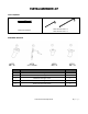
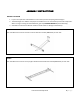
STEP 3
Turn assembled beam over. Insert assembled lifting columns from Step 1 into the beam. The lifting columns are
not centered in relation to feet. Make sure the longer end of foot match that of upper support.
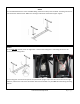
STEP 4
On the inner side of beam, there are eight holes – two for each locking lever. Each lifting column is to be
secured by two locking levers.
Each locking lever consists of axle (shorter end) and handle (longer end). Insert axle into the hole on the right
side first, and then the hole on the left. Please make sure the handle is on your LEFT side when facing the lifting
column.