ELECTRIC HEIGHT-ADJUSTED SIT TO STAND DESK Elite Series Assembly Guide 8/12/2017
Table of Contents CAUTION, USE & LIABILITY .......................................................................................................................... 3 PARTS & HARDWARE LIST ........................................................................................................................... 4 PARTS / COMPONENT DIAGRAMS ......................................................................................................... 5 ASSEMBLY INSTRUCTIONS .......................................
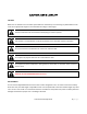
CAUTION, USE & LIABILITY CAUTION Make sure no obstacles are in the desk’s path. Make sure the desk top is not touching any walls. Make sure all cords are of appropriate lengths to accommodate the change in desk height. Read and understand this manual before attempting to install or operate. This product is not intended for use by young children or for those who require supervision Do not sit or stand on the desk. Do not crawl or lie under the desk.
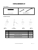
PARTS & HARDWARE LIST TOOLS REQUIRED Allen wrench 4mm x 1 Allen wrench 5mm x 1 Phillips screwdriver HARDWARE INCLUDED 14PCS M6×16 4PCS φ8×135mm 3PCS M5×10 4PCS M6×16 No. HARDWARE LIST Qty A M6x16mm hexagon screw 14 B L-shaped locking lever 4 C M5x10mm hexagon screw 3 D M6x16mm hexagon screw 4 E ST4.
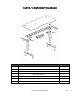
PARTS / COMPONENT DIAGRAMS No.
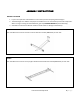
ASSEMBLY INSTRUCTIONS BEFORE YOU BEGIN 1. Lay out all components and hardware to ensure that you have everything listed on Page 5. 2. The desk weighs over 100 lbs. Two people are needed to turn or move desk top and some components. When turning or moving the assembled desk, grab it by SUPPORT BRACKETS (not the desk top). 3. Assemble on soft and non-abrasive surface to avoid scratch or damage to the desk top. STEP 1 Use 5mm Allen wrench to secure foot to column with four Screw A (M6x16mm) on each side.
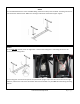
STEP 3 Turn assembled beam over. Insert assembled lifting columns from Step 1 into the beam. The lifting columns are not centered in relation to feet. Make sure the longer end of foot match that of upper support. STEP 4 On the inner side of beam, there are eight holes – two for each locking lever. Each lifting column is to be secured by two locking levers. Each locking lever consists of axle (shorter end) and handle (longer end).
STEP 4 – CONT’D With axles into the holes, push the handle down with your hand toward the lifting column. You should feel some pressure while pushing it down. Once the handle is flush with the beam, use a tool such as a flat-head screwdriver to push it further down. If no pressure is felt while pushing handle down, check whether the top support bracket is installed and secured properly, and whether the handle is on the left. Each lifting column requires two locking levers to secure it correctly.
STEP 6 Now that you have completed the assembly of underframe, it is a good idea to initialize the desk and make sure everything works before assembling the top to the underframe. Turn the underframe over to upright position. 1. 2. 3. 4. Connect height controller cable to the left plug on control box. Connect motor cables to control box. Motor cables can be connected to either port and interchangeably. Switching cables from one port to another may be needed when trouble-shooting.
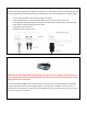
STEP 7-A: INITIALIZING DESK WITH MEMORY CONTROLLER DESK MUST BE INITIALIZED BEFORE YOUR FIRST USE, and may need to be re-initialized (reset) from time to time to work properly. Please note resetting requires more than just a simple power-off and power-on. Use Height Controller to initialize/reset. Press and hold UP and DOWN arrow buttons until blinking 000 appears on the display, and then release the buttons.
TROUBLESHOOTING Issues(s) Desk does not go up or down Columns do not go up evenly. Desk wobbles pretty excessively. Desk is unusually noisy Solution Check all connections. Make sure power cord is plugged into the control box and a power outlet. Unplug the power cord and replug after 10 seconds. Re-initialize the desk. If the problem persists, switch motor cables from one port to another at control box and re-initialize one more time.
ERROR CODE FOR DESK WITH MEMORY CONTROLLER Error Code Solution E1 System failure. Contact dealer. E2 Starting current exception. Unplug power and re-plug after 10 seconds. Reset desk. Contact dealer if problem persists. E3 Starting current exception. Unplug power and re-plug after 10 seconds. Reset desk. Contact dealer if problem persists. E4 Power supply failure. Contact dealer. E5 Desk not synchronized. Unplug power and re-plug after 10 seconds. Reset desk.
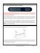
INSTALLING CABLE MANAGEMENT TRAY (SOLD SEPARATELY) Step 1: Locate two screw holes on the backside of the beam and mount the tray as illustrated below with two wing screws and washers Elite Series Assembly Guide 13 | P a g e
Step 2: If adjustment is needed, loosen the screws below, slide the tray to the left or right and tighten the screws.
WARRANTY INFORMATION SCOPE OF WARRANTY Apex Furniture LLC (“ApexDesk”) warrants to the original purchaser its new desk (except for components not warranted under “Exclusions”) manufactured by ApexDesk to be free from defects in material and workmanship under normal use and service.