
Instruction Manual

- 11 -
solution. If the error is large, the instrument needs to be recalibrated.
e) The instrument does not automatically recognize the calibration solution. If the wrong solution is
selected for calibration, the measurement will be completely wrong. To fix this problem, simply
re-calibrate the meter selecting the correct calibration solutions.
f) Place the instrument on a flat and level surface. Do not hold the instrument in hand while
operating.
g) If using Formazin standards for calibration, please make sure to use freshly made Formazin
standard to ensure calibration accuracy.
5 TURBIDITY MEASUREMENT
5.1 Sample Vial Handling
1) 6 sample vials are included in the test kit. The cap is marked with 1
#
to 6
#
, and the bottom of the
vial also has the same number. The number of the vial and the cap should always be the same.
*Pay attention that 1
#
and 2
#
vials are only for low turbidity solution measurement. (< 2 NTU)
2) The vial has been rigorously cleaned and sterilized. They can be used directly for the first time.
For subsequent uses, follow the steps below to perform a thorough cleaning.
⚫ Clean the sample vial inside and outside with detergent → rinse with distilled water or
deionized water multiple times → Rinse the vial twice with the sample solution → Pour the
sample solution into the vial → Close the cap.
5.2 Measurement Preparation
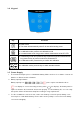
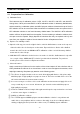
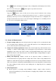
1) Collect sample solution in a clean container, fill sample solution
to the 4/5 position of the sample vial (approximately 18ml), see
Diagram-4, tighten the vial cap.
2) Before measuring, gently shake the sample vial to make sample
solution even and wait for air bubbles to disappear, see
Diagram-5, wait for 2–5 minutes until bubbles eliminate.
3) Wipe the sample vial surface with a microfiber cloth. Ensure that the vial is dry, clean and free
from smudges.
4) Apply 1 drop of silicone oil on the surface of the vial. Wipe with a microfiber cloth to obtain an
even distribution over the entire surface in order to eliminate scratches and smudges and
improve light scattering, see Section 4.1(c) for details.
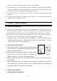
5.3 Measurement Modes
a) Normal Measurement Mode
Diagram- 4
Diagram- 5