MP511 pH/mV Benchtop Meter Instruction Manual APERA INSTRUMENTS, LLC www.aperainst.
Contents 1 Brief Introduction ............................................................................................................ - 3 - 2 Technical Specifications.................................................................................................... - 4 - 3 2.1 2.2 Technical Parameters............................................................................................................ - 4 Other Technical Parameters ..........................................................
1 Brief Introduction Thanks for purchasing and using APERA INSTRUMENTS MP511 pH/mV Benchtop Meter (referred to “meter” as below). Before using this meter please read this instruction manual carefully in order to use and maintain it correctly. On the basis of improving the performance of this instrument constantly, Apera Instruments reserves the rights to update the information of this manual without giving prior notice.
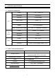
2 Technical Specifications 2.1 Technical Parameters pH Range (-2.00 ~ 19.99)pH Resolution 0.1/0.01 pH Accuracy ±0.01pH±1digit Input Current ≤2×10-12 A Input Impedance ≥1×10¹² Ω Stability ±0.01 pH±1digit/3h Temp. Compensation Range (0 ~ 100)℃(Automatic or Manual) Range -1999mV ~ 0 ~ 1999mV Resolution 1mV Accuracy ±0.1% FS Range -10℃~ 110℃ Resolution 0.1℃ Accuracy 5~ 60℃:±0.5℃±1digit ; Other:±1℃ mV (ORP) Temp. 2.
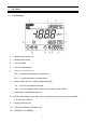
3 The Meter 3.1 LCD Display 1. —Measurement mode icon 2. — Measurement value 3. — Time and date 4. — Units of measurement 5. — Temperature compensation icon: ATC — automatic temperature compensation; MTC — manual temperature compensation 6. — Serial number and icon of data storage and recall M+ — icon for measurement storage; RM — icon for reading recalls; Numbers on the left is serial number. 7. — Temperature measurement and unit 8.—RS232 communication icon.
3.2. Keypad Keypad operations: short press— <1.5 seconds; Long press — >2seconds. Keypad operations and descriptions Keypad Operations Descriptions Turn on/off the power. Attention: Only under measuring mode can the meter be Short press ON OFF CAL operation will be invalid. You need to press and go ON back to measuring mode. Then press < > to turn off. OFF Short press The meter will go to calibration mode. Short pressing again starts calibration.
▲ ▼ M+/RM Short press Long press In MTC mode: press the button to increase or decrease the temperature. The temperature will be altered quickly with long press. In parameter setting mode: press the button to changer numbers or ON/OFF state. In (RM) mode: press the button to alter the storage serial number. Long press to alter quickly. Short press Long Press Short press to store measurements; long press to recall measurements. 3.2 Store, recall and clear readings 3.2.
for 2s. It means the internal storage has been cleared. 3.3 Sockets: REF — Reference electrode socket pH/mV — pH and ORP electrode socket (BNC socket) TEMP — Temperature electrode socket (RCA socket) RS232 — RS232 communication connector socket DC9V — DC9V power socket, Ф2.5, inner “+” outer “-” pH Measurement 3.4 Preparation: 4.1.1. Switch in power, press ON OFF key to turn on. 4.1.2. Short press < MODE > key to switch to mode. 4.1.3.
stable and icon displays, then press < CAL >, LCD flashes 7.00 pH, calibration finishes after several seconds and then flashes, indicating the 1st point calibration has been finished and the 2nd point calibration begins. 4.2.3. Take out pH electrode, rinse it in pure water, allow it to dry and submerge it in pH4.00 buffer solution. Stir the solution briefly and allow it to stay in the buffer solution until reading is stable and icon displays, then press < CAL >, LCD flashes 4.
long time. For a new electrode, 3 points calibration must be performed to make the slope of the meter consistent with the pH electrode. 3.6 Sample Test Rinse pH electrode in pure water, allow it to dry, and submerge it in sample solution. Stir the solution briefly and allow it to stay in the sample solution until the stable value and icon appears on LCD, get the reading which is pH value of sample solution.
conform and return to measuring mode. 4.4.3. Time setting for timing measurement (P2) (a) Momentary press key in mode P2 to enter into mode P3. See picture (4-3) (b) Press < UNIT > key, the “ ” will move to the right and flash. Press <▲> or <▼> key to change when the number is flashing. (c) Press < MODE > key to enter into next parameter setting or press < ENTER > key to conform and return to measuring mode. (d) Factory setting is 0 second.
to alter the number. The upper right is month-day and the lower right is year. (c) Press < MODE > key to enter into next parameter setting or press < ENTER > key to conform and return to measuring mode. 4.4.6. Time setting (P5) (a) Short press key in mode P4 to enter into mode P5, see picture (4-6) (b) Press < UNIT > key, the number will move rightward and flash, press < ▲ > or < ▼ > key to alter the number.
4.5.3. Calibration frequency depends on the solution sample, electrode performance and required accuracy. For high accuracy measurement (≤±0.02pH), you should always calibrate before the tests are performed with highly accurate buffer solutions. For general accuracy measuring (≥±0.1pH), a one-time calibration can be used continuously for one-two weeks. 4.5.4.
4.5.10. The sensitive glass bulb in the front of the combination electrode should not come in contact with hard surfaces. Scratches or cracks on the electrode will cause inaccurate readings. Before and after each measurement, wash the electrode with pure water and then throw off the excess water on the electrode. Do not rub the glass bulb with a tissue for it will affect the stability of the electrode potential and increase the response time.
(a) Check the electrode bulb and see if there are any air bubbles. If any are present, flick the electrode with your wrist until the bubbles have been removed. Be sure to have a firm grip when doing so. (b) Check the pH buffer solution and see if it goes bad or has a bigger error. (c) Restore the meter to factory setting mode (for details see item 4.4.7), then recalibrate it. If the sensor doesn’t work after the above checks, please replace the pH electrode. 4 mV and ORP Measurement 4.1 Sample Test ON 5.
5.2.2. Clean and activate ORP electrode: After the electrode has been used over a long period of time, the platinum surface will get polluted which causes inaccurate measurement and slow response. Please refer to the following methods to clean and activate ORP electrode: (a) For inorganic pollutant, submerge the electrode in 0.1mol/L dilute hydrochloric acid for 30 minutes, then wash it in pure water, then submerge it in the soaking solution for 6 hours.
5.1 System requirements This meter uses “MP500 PC-Link” communication software for RS232 communication. This software requires the computer to meet such requirement: Personal computer (Microsoft Excel 2000 or the version of higher rank) which can operate Windows XP operation system, PC–IBM compatible with XT and CD-ROM driver, RS232 communication port. 5.2 Software interface Software interface: refer to Picture (6-1).
Open “PC-Link” file → Double click “Setup” program → Click “OK”→Click the icon (refer to Picture (6-2) ) → Click “Continue” → Click “Enter”. Picture(6-2) 5.4 Port Connection Connect the meter and PC with RS232 cable and open the MP 500 PC Link Program, the PC will enter into program interface and then click” Select CommID”. The default port of the PC is port#1, Icon will appear on the lower left corner of the LCD screen.
6 Complete Kit 7.1. MP511 pH/mV/Temp Meter 1 unit 7.2. pH/ATC three-in-one combination electrode 1 pc 7.3. 9V multi- adapter (with four kinds of plug) 1 pc 7.4. RS232 communication cable (optional) 1 pc 7.5. MP500 communication software CD (optional) 1 pc 7.6. Operation manual 1 pc 7.7.
APERA INSTRUMENTS, LLC Address: 977 Old Henderson Rd, Columbus Ohio 43220 Tel: 1-614-285-3080 Email: info@aperainst.com Website: www.aperainst.