3-STAGE WATER FILTRATION SYSTEM INSTALLATION INSTRUCTION & OWNER’S MANUAL Ver 1.
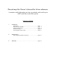
Please keep this Owner’s Manual for future reference. It contains useful information on how to maintain and care for your APEC quick flow water filter system. TABLE OF CONTENT 1. Installation: 2. Maintenance: 3. Warranty ........................................................................... page 15 Preparation ................................................................... Filter housings assembly ................................................. Feed water connection .......................
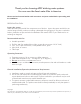
Thank you for choosing APEC drinking water systems. You now own the finest water filter in America. Please read and become familiar with instructions and parts needed before proceeding with the installation. BEFORE INSTALLATION: Inspect the system: Please take the system and all the components out of the box. Inspect the system and all the connection fittings carefully, make sure nothing is damaged during shipping.
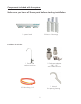
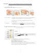
Components included with the system: Make sure you have all these parts before starting installation.
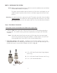
Fitting Types: There are 2 types of fittings provided for connecting the system 1. Quick-Connect (QC) fitting: (no insert, sleeve, or nut) Fig. 1A Fig. 1 How to Connect: - See Fig.1. Push the tubing into the Quick-Connect fitting, then gently pull back on the tubing to make sure connection was secure. - No inserts, sleeve, or nuts are needed to secure the connection. - No Teflon tape! To Disconnect: - See Fig.1A. Push in and hold down on the collet ring square against the fitting.
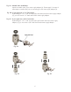
THERE ARE TWO PARTS TO INSTALLING THE SYSTEM: Part I. Part II. Assemble the filters and housings onto the main system Installing the system PART I. ASSEMBLE THE FILTERS AND HOUSINGS ONTO THE MAIN SYSTEM Remove plastic/paper wrappings on the 3 filters, put them into the 3 housings, and assemble the housings onto the main system as follow: 1. See Fig. 2 Stand the 3 housings upright. Make sure each housing has a rubber O-ring in its groove.
PART II. INSTALLING THE SYSTEM Space: Make sure there is sufficient space under the counter for installation (an area of about 15”L x 6”W x 12”H for the system). The system is best installed under the kitchen sink. But if that is not feasible you can install the system anywhere where there is a cold water supply with sufficient water pressure. Mounting: No need to mount the system on the wall. The system can stand in the sink cabinet without mounting, this makes future filter change easy and convenient.
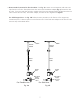
Fig. 5A - Needle Valve Installation. Attach the needle valve (C) to water supply adapter (A). Please apply 5-6 wraps of teflon tape to needle valve prior to connecting it to the water supply adapter (A). Fig. 5B - If your pipe has a 1/2” Connection. By attaching the 1/2” x 3/8” converter (B) to the Male end of the water supply adapter (A), you now have a 1/2” Male and Female water supply adapter. Fig. 5C - If your pipe has a 3/8” Connection.
3. Recommend Connection For Flex Line Riser: See Fig. 6A. Loosen nut and separate cold water riser tube from shut off valve. Gently bend riser tube so that the Feed Water Adapter (Fig 4) fits onto the shut off valve. If your riser tube has no built-in washer, then fit the cone-shaped washer provided onto the riser tube. Connect the riser tube, feed water adapter, and shut off valve together and tighten. For Solid Copper Riser: See Fig. 6B. Follow the same procedure as for flex line.
Fig. 6C Fig. 6D 4. Needle Valve: See Fig. 6C. Screw the Needle Valve onto the Adaptor tightly. Apply 6-8 rounds of Teflon tape onto Needle Valve before attaching it to the Adaptor. To open needle valve: To close needle valve: Turn needle handle counter-clockwise. Turn needle handle clockwise. Test for leaks at this point: Close the Needle Valve (turn needle handle clockwise all the way in to close). Turn ON the cold water supply to the sink faucet.
Step 2: Drill A Hole For The Faucet Drill 1/2” diameter hole for standard faucet. (Air-Gap faucet: drill 1&1/4” hole.) For best results use a 1/2” carbide-tipped masonry drill bit. Wear safety glasses to protect your eyes while drilling the faucet hole. Note: No need to drill a hole if an existing hole is available: a) Spare hole: If there is a spare hole in the sink covered by a chrome cover, simply remove the chrome cover and install the faucet there.
Step 3: Mounting The Faucet 1. Mount the faucet as shown in Fig.7. 2. Connect the White line to the faucet. 3. The faucet has two operating positions: Push black lever down to fill a glass of water, or lift lever up into a locked position to fill a container or to drain the storage tank. Counter Top Chrome Base Fig. 7 Counter Top Opening Black Locating Washer Lock Washer Insert Lock Nut Sleeve Compression Nut Step 4: Positioning The System 1.
Step 5: Connecting The System Summary of Tubing Connections: There are 2 connections: See Fig 8 Point A to X: Connect system to COLD water supply — Red tubing. Point H to Z: Connect product water from 3rd-stage output to faucet — White tubing. Fig.
Details on Tubing Connections: To ensure a smooth and correct installation, please connect the water lines following the sequence and order outlined below. Refer to Fig.8 for proper point locations. 1. Point Z Faucet connection: Tubing color: Fitting type: White tubing. Connect the WHITE tubing to the base of the faucet. Quick Connect Fitting. Simply push White tubing into Quick Connect fitting. No Insert, Sleeve or Nut needed here. (Attach threaded end of faucet adapter to the faucet metal stem.
Option: Ice-maker Connection If you want to connect product water from the System to your ice-maker, you will need: • One T-fitting, preferably the quick-connect type fitting • Extra ¼ “ tubing long enough to go from the system to your ice-maker • Optional: One shut-off valve, preferably the quick-connect type. See Fig.9. Before connecting the product water line from Point Z to H, add a T-fitting near point H to divert product water to both the ice-maker and the faucet. Fig.
FILTER CHANGE INSTRUCTIONS How To Replace Stages 1, 2, 3 Filters: 1) Turn OFF cold water supply to system. Lift up faucet lever briefly to relief the built-up pressure inside the system. This will make opening the housings easier. 2) Open housing: Have the System standing upright. Slip the plastic wrench onto the #1 housing. Looking down from a top view, you should open the housing turning clockwise. If necessary, lay System down on the floor to get a better leverage.
LIMITED PRODUCT WARRANTY Scope APEC takes pride in selling a superb line of products, including this water filtration system (“Product”). As such, APEC expressly warrants to the original purchaser that, for a period of one (1) year from the date of purchase, the Product will be reasonably free of defects in materials and workmanship.
CONDITIONS THAT RENDER THIS LIMITED PRODUCT WARRANTY VOID THIS LIMITED PRODUCT WARRANTY SHALL BE VOID IF: 1. The Product is not operated in compliance with normal municipal water conditions for which the particular model of this Product is intended. 2. The person seeking to invoke the warranty is not the original purchaser. That is, this Limited Product Warranty only extends to original purchasers. 3. The is purchased used. That is, this Limited Product Warranty only covers new products. 4.
Advanced Purification Engineering Corp. 1320 S Johnson Drive City of Industry, CA 91745 For questions or comments please visit our website at: FreeDrinkingWater.com For technical support contact us at: Techsupport@freedrinkingwater.