
Instructions / Assembly


4
INSTALLING THE SYSTEM
Space: Make sure there is sufficient space under the counter for installation (an area of about
14”L x 6”W x 6.5”H for the system, 11”D x 18”H for tank).
The RO system is best installed under the kitchen sink. But if that is not feasible you
can install the system anywhere where there is a cold water supply with sufficient
water pressure for the chosen RO model, and an outlet to drain off the drain water
from the system.
Feed Water: RO systems are designed to treat both hard and soft water and can handle incoming
TDS levels up to 2000ppm.
Note: Please remove the 2 white plastic zip ties on the RO-QUICK90 system. This is
for shipping protection only.
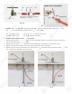
Step 1: Feed Water Connection
The RO system must be connected to the COLD water supply only!
1. Locate the Cold water supply valve under the kitchen sink (the round or oblong handle on
the right side). Turn off the incoming cold water completely by turning the shut off handle
clockwise.
Note: If the cold water shut off valve can not turn off the water, the main water supply
to the house must be shut off for the installation. Another option is to use a “self
piercing saddle valve” from APEC or from a local hardware store.
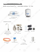
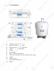
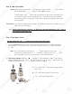
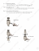
2. Feed Water Adaptor (1/2” or 3/8”): See Fig. 1. The Feed Water Adaptor comes with a
separate Needle Valve. The Adaptor goes inline onto your 1/2” or 3/8” cold water pipe. The
Needle Valve portion screws onto the Adaptor as shown in Fig. 2.
Fig. 1
A. 1/2” x 3/8” Male-Female Water Supply Adapter
with O-ring.
B. 1/2” x 3/8” Female-Male Converter with O-ring.
C. 1/4” x 1/8” Male Needle Valve.
4
IN
ST
ST
AL
AL
LI
LI
N
NG
THE
S
Y
S
TE
M
Sp
ace
:
Make sure there is su
ff
icient
s
s
pa
pa
ce under the counter
f
or install
at
t
ioio
n
n
(a(a
n
n
area o
f
about
14”L x
6
”W x
6
.5
”H
H
f
f
oror
tt
hehe
system, 11”D x 1
8
”
H
f
or tank).
The RO system is bes
t
t
i
in
t
st
alled under the kitchen sink. But i
f
that is not
f
easible you
c
an install the system anywhere where there is a cold water supply with su
ff
icient
water pressure
f
or the chosen RO model, and an outlet to drain o
ff
the drain wat
er
f
rom the system.
Feed Water:
RO
RO
s
ystems are designed to treat both
ha
ha
rd
rd
a
a
nd
nd
so
f
t water and can handle incom
in
in
g
g
TDTD
S
S
le
l
vels up to 2000ppm
.
No
o
tete
:
:
Pl
Pl
ease remove the 2 white
pl
as
s
ti
ti
cc
z
zi
p
ties on the RO-QUICK90 s
ysys
tete
m.m.
This is
pp
y
y
for shipping protection on
ly
y
.
pp g p
y
y
St
ep
1: Feed Water Conne
ct
ct
io
io
n
n
The RO system mu
st
t
bb
e
e
coco
nn
ected to the COLD water supply only!
y
pp
y
y
1. Locate the
Co
l
d
water supply valve under the kitchen sink (the round or oblong handle on
the ri
gh
t side
).
Turn o
ff
the incomin
g
cold water com
pl
etel
y
by
turni
ng
the shut o
ff
handle
c
l
oc
kw
is
e.
N
ote: I
f
the cold water shut o
ff
valve ca
n
n
nono
t
t
tutu
r
rn
o
ff
the water, the main water
s
s
upup
pl
pl
y
y
to the house must be shut o
ff
fo
o
r r
th
th
e
e
in
in
stallation. Another option is to
us
us
e
e
a
a
“sel
f
pi
erci
ng
saddle valve”
f
rom
AP
AP
ECEC
or
f
rom a local hardware store.
2.2.
Feed Water Adaptor (1/2” or
3/
/
8”
8
):
):
See
F
i
g. 1. The Feed Water A
da
a
ptpt
oror
c
c
omes with a
s
eparate Needle Valve. The A
da
a
ptpt
oror
g
oes inline onto your 1/2” or 3
/8
8
””
co
co
ld
ld
water pipe. The
N
eedle Valve portion screw
s
s
onon
to
to
t
t
h
he
Adaptor as shown in F
i
g. 2.
F
i
g.
1
A.
1/2” x 3/8” Male-
F
Fe
male Water Supply Adapte
r
with O-ring.
B. 1/2” x 3/8” Female-Male Converter with
O
O
-r
-r
inin
g
g.
C.
C
1/4” x 1/8” Male Needle Valve
.