
Instructions / Assembly


27
Part II: Trouble-Shoot Guide
For Newly Installed RO System
After installation, if you encounter any of the problems described below, please follow this guide to trouble-
shoot. In most cases, the problem is quickly solved by following this guide.
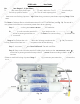
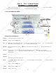
Non-Pump RO HEAD DIAGRAM
52+HDG3RLQWV,GHQWL¿FDWLRQ
Point A: Feed water inlet into Stage-1 filter
Point B: Stage-2 filter’s output port .
Point C: Automatic-Shut-Off (ASO) valve. For Permeate Pumped systems, the permeate pump replaces the
ASO valve, it serves both as a pump and an auto-shut-off valve.
Point D: Stage-3 Membrane housing inlet port. Feed water from Stage-3 filter enters the Membrane at
this port.
Point E: Check Valve. The filtered water from the Membrane passes through this Check Valve
before entering the storage tank. The Check Valve blocks the tank water from back-flowing into
the membrane.
Point F: T-fitting on Stage-4 filter. This end of the T-fitting connects to the CLEAR pure water line.
Point G: T-fitting on the Stage-4 filter. This other end of the T-fitting connects to the YELLOW pure water
line which goes to the tank’s valve.
Point H: The output end of Stage-4 filter. Pure water leaves Stage-4 filter via this port, and flows onto the
dispensing faucet.
Point I: Stage-1 filter’s output port.
Point J: Stage-4 filter’s input port.
Point K: Stage-2 filter’s input port.
Fig. 16
Stage 1
Stage 2
Stage 3
Stage 4
2
7
P
a
rt II: Tr
ou
b
b
l
l
ee
-
S
S
h
oo
t
Gu
i
de
For Newly
I
I
nn
ss
t
t
a
a
l
l
led RO System
y y
Af
f
tete
r r
in
in
stst
al
a
lation, i
f
you encounter any
o
f
f
th
th
e
pr
pr
ob
ob
l
le
ms described below, please
f
f
olol
lo
lo
w w
th
th
is guide to trouble-
shsh
oooo
t.
t.
In most cases, the problem is
q
q
uiui
ckck
lyly
s
s
ol
l
ved by
f
ollowing this guide.
N
No
n-Pu
mp
RO HEAD DIA
G
RA
M
52+HDG3RLQWV,GHQWL¿FDWLRQ
P
o
int
A
:
F
e
ed water inlet into Stage-1
f
ilte
r
P
oi
nt
B
:
Stag
e
-
2
f
ilt
e
r’
s
ou
t
pu
t
port .
P
o
in
n
t
t
C
C
:
:
A
Au
tomatic-Shut-O
ff
(ASO) valve.
Fo
Fo
r
r
PePe
rm
rm
eate Pumped systems, the per
me
me
at
a
e
pu
mp replaces the
ASO valve, it serves both as a
p
p
um
u
p
a
an
d an auto-shut-o
ff
valve.
PoPo
i
in
t D
:
Stag
e
-
3 Membrane housin
gg
inin
lele
t
t
port. Feed water
f
rom Stage-3
f
il
il
tete
r r
en
en
t
te
rs the Membrane at
this port.
P
oi
nt E
:
Check
V
alve. The filt
er
r
eded
water from the Membrane p
as
s
sese
s s
thth
ro
ro
ugh this Check Valve
V
V
be
f
ore enter
in
n
gg
thth
e e
st
st
or
age tank. The Check Valve bloc
ks
ks
tt
he
he
tt
a
an
k water
f
rom back-
f
lowing into
th
e
m
e
m
b
r
a
ne
e
.
.
P
oi
nt F
:
T
-fitting on Stage-4 filter. This end of the T-fitting connects to the CLEAR pure water line.
TT
P
o
int
G:
T
-fitting on the Stage-4 filter. This other end of the T-fitting connects to the YELLOW
pp
urur
e e
w
wa
ter
TT
l
ine which goes to the tank’s valv
e.
P
oi
n
t
H
H
:
Th
e
output end
of
Stage-4
f
ilter. P
ur
ur
e
e
wa
wa
ter leaves Stage-4
f
ilter via this p
or
r
t,
t,
a
a
nd
nd
f
lows onto the
d
ispensing
f
aucet.
PoPo
inin
t
t
I
I
:
Stag
e
-
1
f
ilt
e
r’
s
ou
t
pu
t
por
t.
.
P
Po
i
nt
J
:
Stag
e
-
4
f
ilt
e
r’
s
i
npu
t
p
or
or
t.
t.
P
oi
nt K
:
Stag
e
-
2
f
ilt
e
r’
s
i
n
pupu
t
t
p
p
or
or
t.
+
HD
G
3R
LQ
WV
,
GH
QW
L¿
FD
WL
RQ
Fig. 1
6
Stage
1
Stage
2
Stage
3
Stage
4
4