
Instructions / Assembly


23
Part I: RO BASICS
This section provides basic concepts on how an RO system works, how it performs in relation to your
house’s water condition. We hope this information helps keep your RO system running at top
performance for years to come.
1) Basic Terms
GPD = Gallons Per Day (flow rate)
PSI = Pounds per Square Inch (pressure)
TDS = Total Dissolved Solids (contaminants)
PPM = Parts Per Million (unit used to measure TDS level)
TDS Meter = A digital meter for measuring the TDS level in the water
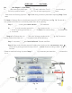
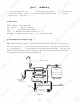
2) Flow Diagram for 4-Stage RO System:
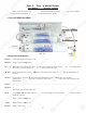
Fig.15 below shows how water flows through the RO system from Feed point to Output point.
Input water starts from Main Water Supply, going through stages 1, 2 pre-filters, then enters the
stage-3 membrane. Product (filtered) water from the membrane feeds the storage tank; the “drain
water” from the membrane drains out through the drain line. Product water from the tank passes
through stage-4 filter before reaching the dispensing faucet.
Fig. 15
APEC RO-QUICK SYSTEM FLOW DIAGRAM
1st Stage Filter
4th Stage Filter
2nd Stage Filter
PRODUCT
WATER
TANK
FAUCET
MAIN
WATER
SUPPLY
FEED WATER
NEEDLE VALVE
MAIN WATER SUPPLY
SHUT-OFF VALVE
CHECK VALVE
(BUILT IN)
3rd Stage
R.O. MEMBRANE
PRODUCT WATER
IN
OUT
FLOW RESTRICTOR
(BUILT IN)
INLET
TANK
BALL
VALVE
AUTO SHUT-OFF
VALVE
DRAIN WATER
DRAIN
23
P
a
rt I
:
:
R
R
O
O
BA
S
I
C
S
ThTh
is
is
section provides basic conc
ep
ts
ts
o
o
nn
ho
h
w
w
an RO system works, how it p
er
r
fofo
rmrm
s s
in
in
relation to you
r
ho
ho
use’s water condition. We hop
e
e
th
th
is
is
i
i
nf
nf
ormation helps keep your RO syst
em
m
r
r
un
un
ni
ng at top
pe
r
f
ormance
f
or
ye
ars to come.
1)
Basic Terms
GPD = Gallons
Pe
P
r Day (
f
low rate
)
PS
I = P
o
unds
pepe
r
r
Sq
Sq
uare Inch
(
pr
essure
)
TDS = To
ta
ta
l
l
DiDi
ssss
ol
o
ved Solids (contaminants
)
P
PM =
Pa
Pa
rt
rt
s
s
Pe
Pe
r Million (unit used to measure
TD
TD
S
S
le
le
ve
l)
TDS
Me
Me
te
te
r
r
= A digital meter
f
or measuri
ng
g
t
he
he
T
T
DS
D
level in the wate
r
2)
2)
Flow Diagram
f
or 4-Stage R
O
O
SySy
stst
em
em
:
F
i
g.15
below shows how water
fl
fl
o
ow
s through the RO system
f
rom Feed point to Output point.
I
nput water starts
f
rom
Ma
Ma
inin
W
W
ater Supply, going through stages 1, 2 pre-
f
ilters, then enters the
s
t
ag
e-3 membrane. Pr
od
d
uc
uc
t
t
(
(f
iltere
d)
water
f
rom the membrane
f
eeds the stora
ge
tank; the “drain
water”
f
rom the membrane drains out through the drain line. Product water
f
rom the tank pass
es
s
through stage-4
f
ilter be
f
ore reaching the dispensing
fa
a
uc
uc
et
e
.
F
i
g. 1
5
A
PEC
RO-
RO-
QUICQUIC
K
K SY
STEM FL
O
W DIAGRAM
1st Stage Fi
l
te
r
4
t
h
Stage Fi
l
te
r
2
nd Sta
g
e Filter
P
RODUCT
WA
TER
A
A
TA
NK
FA
UCE
T
MAIN
N
WA
A
TERTER
A
A
A
SUPP
UPP
LYLY
FEED
D
WA
TER
TER
A
A
NEEDLE
VA
LV
E
MAIN
WA
TER SUPPLY
AA
S
HUT-OFF
VA
LV
E
CHEC
K
VA
LV
E
(
BUILT IN
)
3
rd Sta
g
e
R.O. MEMBRANE
PROD
UCT
WA
TER
A
A
IN
OUT
FLOW
FLOW
RES
TRIC
TO
R
(
BUILT IN
)
INLET
TA
TA
NK
BALL
VA
LV
E
AU
T
O
SHUT-
O
FF
VA
LV
E
DRAIN
WA
TER
A
A
DRAIN