
Instructions / Assembly


15
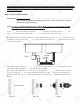
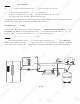
3. Point W - Drain water connection:
Tubing color: Black tubing. Connect the BLACK tubing from the RO to the Drain Saddle.
Fitting type: Simply push the Clear tubing into the Quick Connect fitting. No Inserts, Sleeves or Nuts
are needed to secure the connection. No Teflon tape needed here.
4. Point A - System water inlet (to Stage 1 pre-filter) connection:
Tubing color: Red tubing. Connect the RED tubing from the Feed Water Valve to the RO’s stage -1
prefilter.
Fitting type: Quick Connect fitting See Fig. 10D (Page 12). Simply push the Red tubing into the QC
fitting. No Inserts, Sleeves or Nuts are needed to secure the connection. No Teflon tape
needed here.
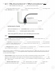
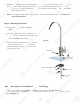
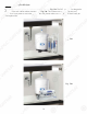
5. Point H - Stage-4 filtered water to faucet connection:
Tubing color: Clear tubing. Connect the CLEAR tubing from the faucet base stud to the Stage-6 filter’s
outflow end at point H. (See “Flow -->” arrow on the filter is the output to faucet at Point Z.)
Fitting type: Quick Connect: Simply push the Clear tubing into the QC fitting. No Inserts, Sleeves or
Nuts are needed to secure the connection. No Teflon tape needed here.
6. Point G - Stage-4 filter’s T-fitting connection:
Tubing color: Yellow tubing. Connect the YELLOW tubing to Stage-5 filter’s T-fitting.
Fitting type: Quick Connect: Simply push the Yellow tubing into the QC fitting. No Inserts, Sleeves or
Nuts are needed to secure the connection. No Teflon tape needed here.
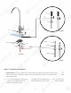
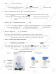
7. Point Y - Tank’s input & output connection:
Prepare tank: See Fig.12. Apply 6-8 wraps of Teflon tape to tank’s threaded Output stem on top of tank.
Screw tank Valve onto Output stem.
Tubing color: Yellow tubing. Connect the YELLOW tubing from Stage-5 T-fitting to the tank’s valve.
Fitting type: Quick-Connect fitting on ball valve. Simply push Yellow tubing into valve port.
Standard 4-gallon Tank Diagram:
Tank Ball Valve
OFF Position ON Position
Fig. 12
Important:
DO NOT TOUCH
the Air Valve, It’s
a pre-pressurized
tank, release or
add air will affect
tank normal
function.
(Note: If the unit comes with a UV Light, connect the Yellow tubing to the T- fitting on the
UV, as the Stage 4 filter will not have a T-fitting).
15
3
. Point
W
W
-
-
DD
ra
ra
in water connection
:
Tu
Tu
bi
bi
ng
ng
c
c
olor: Black tubi
ng
. Connect the
BL
L
AC
AC
K K
tubi
ng
from the RO to the Dr
ai
i
n
n
Sa
dd
dd
le
le
.
Fi
i
tt
tt
in
i
g type: Simply push the Clear tubi
ng
g
i
i
nt
nt
o the Quick Connect
f
itting.
N
N
oo
In
In
sese
rt
rt
s, Sleeves or Nuts
are needed to secu
re
re
t
t
hehe
c
c
on
on
nection. No
T
eflon tape needed
hehe
re
re
..
T
T
4.
4
Point A - System water inlet (to
St
St
ag
ag
e 1 pre-
f
ilter) connection
:
Tubing color: Red tubing. Connect the RED tubing from the Feed Water Valve to the RO’s stage -1
pre
f
ilter.
F
itting type: Quick Connect
f
itting Se
e
Fig. 10D
(
Page
12
2
)
)
. Simply push the Red tubing into the
QC
QC
f
itt
in
n
g.
g
No Inserts, Sleeves or Nuts are nee
de
de
d
d
toto
secure the connection. No Te
f
lon
ta
ta
pepe
ne
ne
eded
ed
ed
h
e
r
e
.
5
. Point H
-
-
SS
tata
g
ge
-4
f
iltered water to
f
aucet
co
o
nnnn
ec
ec
t
ti
on
:
Tu
bi
ng
ng
c
c
ol
o
or: Clear tubing. Connect the
CL
CL
EA
A
R
R
t
tu
bing from the faucet base stud t
o
o
thth
e
e
S
St
age-6 filter’s
outflow
e
n
d
a
t
w
po
i
nt H.
(
(
SeSe
e
e
“
“
Fl
F
ow --
>
”
arrow on the
f
ilter is
t
t
he
he
o
o
ut
pu
pu
t to
f
aucet at Point Z
.)
Fi
Fi
t
tt
ing type: Quick Connect: Sim
pl
pl
y
y
pupu
sh
sh
the Clear tubing into the QC
f
i
tt
tt
inin
g.g.
NN
o
o
Inserts, Sleeves o
r
N
uts are needed to
s
s
ecec
u
ur
e the connection. No Te
f
lon tape n
ee
ee
dede
d d
h
he
re.
6
. Point G - Stage-4
f
il
te
e
r’r’
s s
T-T-
fi
fi
tt
t
i
in
g connection
:
Tubing color: Yellow tub
in
n
g
g.
C
C
onnect the YELLOW tubing to Stage-5
f
ilter’s T-
f
itting.
F
itting type: Quick Connect: Simply push the Yellow tubing into the QC
f
itting. No Inserts, Slee
ve
e
s
s
or
o
N
uts are needed to secure the connection
.
.
No
N
Te
f
lon tape needed here.
7
. Point Y - Tank’s in
pu
t & ou
tp
ut connectio
n:
P
r
ep
p
arar
ee
ta
ta
nk: See F
i
g.12. Apply
6
-8 wrap
s
o
f
f
TeTe
fl
fl
on tape to tank’s threaded Out
pu
u
t
t
stst
em
em
on top of tank.
p
Screw tank Valve onto Outp
ut
ut
s
s
tete
m
m.
TuTu
bi
bi
n
ng
color: Yellow tubing. Connect t
he
he
Y
EL
L
LO
LO
W tubing from Stage-5 T-fitt
in
g
g
to
to
t
t
he
he
tank’s valve.
Fi
F
ttin
g
ty
pe
: Quick-Connect
f
ittin
g
on
on
b
b
alal
l
l
valve. Sim
pl
y
pu
sh Yellow tubi
ng
ng
i
i
ntnt
oo
v
va
lve
po
rt.
S
St
andard 4-gallon Tank Diagr
am
m
:
:
T
Ta
nk
B
a
ll
Va
lv
e
O
FF P
os
iti
on
ON
Positio
n
F
i
g. 12
I
m
po
rtant
:
DO
N
OT
O
T
OU
CH
th
e
e
AiAi
r
r
Va
V
lve,
I
t’
s
aa
prpr
e
e-
pressurized
ta
ta
nk
,
release o
r
ad
d air will a
ff
ect
ta
nk
n
or
ma
l
f
unction.
(
N
ote
:
I
f
the unit c
om
om
es
es
w
w
it
it
h
a UV Ligh
t
, connect the Yellow t
ub
ub
inin
g
g
to
t
the T-
f
itting on the
UV, as th
e
e
St
St
agag
e 4
f
ilter will not have a T-
f
itting
).