
Instructions / Assembly


8
MOUNT DRAIN
SADDLE AT
EITHER
LOCATION
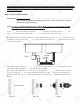
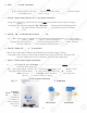
Step 2: Drain Saddle Installation
Important: DO NOT REMOVE the black drain tubing from the RO system system! If you
need to extend the drain tubing please use a union connector to connect
additional length of tubing.
Note: To avoid possible drainage noise, mount drain line as low as possible on the
vertical tailpiece, or on horizontal tailpiece.
There is constant water pressure “packed” inside the RO system which blocks the drain water from
backing-up into the system. So the drain water is “forced-drained”, not “gravity-drained”.
1. See Fig. 6. The drain saddle assembly should be installed above the trap and on the vertical or horizon-
tal tailpiece. To reduce the drainage noise, mount the drain line as low as possible above the trap, or on
the horizontal tailpiece.
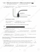
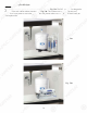
2. Select the location of the hole and drill a 1/4’’ hole through one side of the drain pipe then put the
self-adhesive black sponge around the hole location (See Fig. 7A and 7B).
Next, align and install the drain saddle clip with the tubing connection port onto the black sponge.
This will cushion any gap between the saddle and the pipe. Make sure the hole on the sponge is
thoroughly punched out, and is aligned to the hole on the saddle to complete the installation (See
Fig. 8)
Fig. 6
Fig. 7A Fig. 8
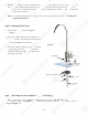
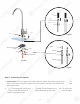
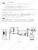
Test for leaks after the system is completely installed: Close the Needle Valve (turn needle handle clock-
wise all the way in to close). Turn ON the cold water supply to the sink faucet. If the Needle Valve or the
Adaptor leaks, check the connection and try applying more Teflon tape or tighten the brass nut some
more to stop the leak.
Fig. 7B
8
MO
MO
UN
UN
T DRAI
N
SA
SA
DD
LE
AT
EITHER
L
O
CA
TION
A
A
St
S
ep 2: Drain Saddle Installati
on
n
Im
p
ortant
:
DO NOT REMOVE the black drain tubing from the RO system system! If you
need to extend the drain tubing please use a union connector to conne
ct
additional length o
f
tubing
.
N
ote
:
To avo
id
d
p
p
ossible drainage noise, mount
dr
dr
aiai
n
n
line as low as possible on t
he
e
p
p
g
,
p
vertic
al
al
tt
ai
ai
lp
l
iece, or on horizontal tai
lp
p
ieie
cece
.
.
p,
p
p
There
is
s
c
c
on
on
stst
ant water pressure “packed” in
si
de
de
tt
he
he
R
O system which blocks the drai
n
wawa
tete
r r
f
fr
om
back
in
n
g
g
-u
-u
p into the system. So the drain
wa
a
te
te
r
r
is
is
“
“
f
fo
rced-drained”, not “gravity-drai
ne
ne
d”
d”
.
1.
.
Se
S
e
Fi
Fi
g.
6
. The drain saddle assembl
y
y
sh
sh
ouou
ld
ld
be installed above the trap
a
nd
nd
o
o
n
n
th
h
e
e
vertical or horizon-
tata
l
l
tailpiece. To reduce the drain
ag
g
e e
nono
isis
e
e,
mount the drain line as low a
s
po
po
ss
s
ibib
le
l
above the trap, or on
the horizontal tailpiece.
2
2.
Select the location o
f
the hole
an
n
d
d
drdr
il
il
l
l
a
1/4’’ hole through one side o
f
t
t
hehe
d
d
rain pipe then put the
s
el
f
-adhesive black sponge a
ro
o
unun
d
d
the hole location
(S
ee
F
i
g
. 7A
and
A
7B
7B
)
).
N
ext, align and install the dr
ai
ai
n
n
sa
sa
ddle clip with the tubing co
nn
n
ecec
titi
onon
p
p
o
or
t onto the black sponge.
This will cushion any
gaga
p p
be
be
tw
w
een the saddle and the pipe. M
ak
ak
e e
su
su
re
re
the hole on the sponge is
thorou
gh
ly
punched
oo
ut
ut
,,
an
an
d
d
is aligned to the hole on the sadd
le
le
t
t
o
o
c
co
mplete the installation
(S
ee
F
i
g
.
8
)
Fig.
6
Fig. 7
A
F
i
g. 8
Test for
l
l
eaea
ks
ks
a
a
fter the system is completely inst
al
l
le
le
d:
d:
C
C
lo
lo
se the Needle Valve (turn ne
ed
d
le
le
hh
an
an
dl
d
e clock-
y
p
y
(
wise
a
a
ll
ll
tt
he
he
way in to close). Turn ON the col
d
d
wa
wa
te
te
r
r
supply to the sink faucet. If the
NeNe
eded
l
le
Valve or the
y ) pp y
Ad
d
ap
ap
to
to
r
r
leaks, check the connection and tr
y
y
apap
pl
yi
ng
more Teflon t
ap
e or t
ig
ht
en
e
t
he
e
b
b
rass nut some
p,
y
y
p
py g p g
mo
m
re
re
to stop the leak.
p
F
i
g. 7
B