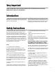
® ENGINE INSTRUCTION MANUAL 4 3 5 2 7 1 6 G26 Air G26/231 Marine G231 Heli G38 G62 GT80 Twin G45 1 2 3 4 5 6 7
Table of Contents Introduction . . . . . . . . . . . . . . . . . . . . . . . . . . . . . . . . . . . . . . . . . . . . . . . . . . . . . . . . . . . . . . . . . . . . 3 Safety Instructions . . . . . . . . . . . . . . . . . . . . . . . . . . . . . . . . . . . . . . . . . . . . . . . . . . . . . . . . . . . . . . . 3 Support Equipment . . . . . . . . . . . . . . . . . . . . . . . . . . . . . . . . . . . . . . . . . . . . . . . . . . . . . . . . . . . . . . 4 Mounting the Engine . . . . . . . . . . . . . . . .
Very Important FAILURE TO READ AND FOLLOW THESE INSTRUCTIONS BEFORE YOU PROCEED MAY RESULT IN ENGINE DAMAGE AND THE VOIDING OF YOUR WARRANTY! Introduction Congratulations on purchasing a Zenoah® engine. Cared for properly, these high-quality, finely crafted engines will offer many years of reliability. This instruction manual has been developed to ensure optimum performance from the Zenoah engine you have purchased.
Safety Instructions (continued) Caution Disassembly 1. Model engines get very hot while running. Do not attempt to handle them until they have cooled. The Zenoah engine can be disassembled or reassembled without any specific difficulties. Refer to the Engine Maintenance Section for specific instructions on these procedures. If you need service to your Zenoah engine, please send your engine to the authorized service center at the following address: 2.
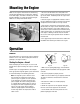
Mounting the Engine Make sure the engine is mounted on the aircraft using aircraft grade plywood that’s at least 6mm in thickness for the G26 engine, and 10mm in thickness for the G38 through GT80 twin, or a mount of equivalent strength. Make sure it’s firmly mounted with 4 bolts. 1. Be sure to set flat washers or a metal plate on the reverse side of the mount to prevent the bolts from sinking into the mount. Periodically check the engine mount for loose bolts. 2.
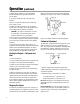
Operation (continued) 8. Quickly flip the propeller in a counterclockwise direction according to the procedure described in the note above. 9. The engine should start after a few flips of the propeller. body, or the throttle valve should be closed completely. Installation of a “stop” or “kill” switch is recommended. Red Lead Black Lead 10. Be sure to open the choke when the initial firing of the engine is heard. 11.
Operation (continued) High-Speed Needle: Turning this needle clockwise makes the gas mixture leaner, and turning it counterclockwise makes it richer. Set this needle at a position which is 1/4 open from the maximum rpm position while the aircraft is on the ground. When the engine has just started and is not warm enough, there may be insufficient acceleration and the engine may die. Be sure to allow the engine to warm up at idle for a few minutes before conducting normal operation.
Engine Care and Maintenance (continued) c. Remove the rotor by using the puller. Do not hit the crankshaft with the plastic hammer, as this can increase the runout of the shaft. 7. Remove the mounting plate. 8. Remove the four bolts from the crankcase. 9. Tap around the case fitting side gently with the plastic hammer and slowly separate the crankcase from the cylinder block. 10. Pull out the crankshaft with the piston, bearings, and other parts attached. 7.
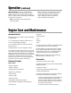
Troubleshooting Guide for Gasoline Engines a) The engine does not start. The crankshaft does not rotate Seizure, intrusion of a foreign substance The crankshaft rotates The fuel has not been fed to the carburetor Disassemble and repair Clogging inside the carburetor Disassemble and clean Clogging of the fuel piping Clean The fuel has been fed to the carburetor No compression (normally 7 kg/cm2 99.
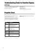
Troubleshooting Guide for Gasoline Engines (continued) In the event that none of the above procedures results in the engine running properly, contact our service department for suggestions at: Horizon Hobby, Inc. 4105 Fieldstone Road Champaign, IL 61822 Phone: 217-355-9511 (M–F 8:00–5:00 CST) Propeller Chart This chart enables you to select the best propeller for initial set-up of your Zenoah® engine. Remember, it’s imperative to balance each propeller prior to installation onto your Zenoah engine.
Engine Specifications OUTSIDE DIMENSIONS (MM) Items Length Width Height Operating RPM Optional Mufflers G26A 139mm 105mm 181mm 2,000–10,000 BIS07123 G26M 139mm 105mm 181mm 2,000–10,000 G231 HELI 142mm 105mm 181mm 3,000–11,000 G231 MARINE 142mm 105mm 181mm 3,500–15,000 — — — G38 170mm 130mm 215mm 2,000–9,000 BIS07138 G45 152mm 130mm 185mm 2,000–10,000 BIS07145 G62 162.5mm 140mm 185mm 2,000–10,000 BIS07163 GT80 191.
Exploded Illustration G26/G231 Index No. 1-1 1-2 2-1 2-2 3 4 5 6 7 8 9 10 11 12 13 14 15 16 17 18 19 20 21 22 23-1 23-2 24-1 24-2 25-1 25-2 26 27 28 29 30 31 32 33 34 35 36 37 38-1 38-2 39 40 41 42 43 44 45 46 47 48 49 50 12 Q’ty per unit Part No. ZEN2601 ZEN2301RC ZEN2601M ZEN23102M ZEN23103M ZEN2304M ZEN23105M ZEN23106M ZEN23107M ZEN23108 ZEN2309 ZEN23110 ZEN23111 ZEN23112 ZEN23114 Description CYLINDER CYLINDER CYLINDER CYLINDER JACKET JOINT O-RING 3X40 O-RING 1.5X15.
Exploded Illustration G38 Index No. 1 2 3 4 5 6 11 12 13 14 15 16 17 18 19 20 (Standard Accessory for G380PU) Part No. Description ZEN3801 CYLINDER ZEN3802 INSULATOR ZEN3803 CARB GASKET ZEN3804 INSULATOR SCREW ZEN3805 INSULATOR GASKET ZEN3806 MUFFLER ASS’Y ZEN3811 MUFFLER GASKET ZEN3812 MUFFLER BOLT ZEN3813 CRANKCASE ZEN3814 CASE BOLT ZEN3815 CASE WASHER ZEN3816 CASE PLUG ZEN3817 PLUG GASKET ZEN3818 PISTON ZEN3819 PISTON RING ZEN3820 PISTON PIN Q’ty/ unit 1 1 1 2 1 1 1 2 1 4 4 1 1 1 1 1 Index No.
Exploded Illustration G45 Index No. 1 2 3 4 5 6 7 8 9 10 11 13 14 15 16 17 18 19 20 14 Part No. ZEN4501 ZEN4502 ZEN4503 ZEN4504 ZEN6204 ZEN4506 ZEN4504 ZEN6207 ZEN6208 ZEN6209 ZEN6210 ZEN4513 ZEN6213 ZEN6214 ZEN6215 ZEN6216 ZEN6217 ZEN6276 ZEN4520 Description CYLINDER INSULATOR INSULATOR GASKET BOLT CARBURETOR GASKET CYLINDER GASKET BOLT MUFFLER MUFFLER GASKET MUFFLER BOLT MUFFLER NUT CRANKCASE COMP.
Exploded Illustration G62 * (Accessory for G620PU-1) Index No. Part No. Description 1 ZEN6201 CYLINDER 2 ZEN6202 INSULATOR GASKET 3 ZEN6203 INSULATOR 4 ZEN6204 CARBURETOR GASKET 5 ZEN6205 CYLINDER BASE GASKET 6 ZEN2309 CYLINDER BOLT 7 ZEN6207 MUFFLER 8 ZEN6208 MUFFLER GASKET 9 ZEN6209 MUFFLER BOLT 10 ZEN6210 MUFFLER NUT 11,12 ZEN6211 CRANKCASE COMP.
Exploded Illustration GT80 Index No. 1 2 3 4 5 6 7 8 9 10 11 12 13 14 15 16 17 18 19 20 21 Part No.
Warranty Information Zenoah® engines are guaranteed against workmanship and manufacturing defects for a period of 3 years from the original date of purchase. This warranty is limited to the original purchaser and is not transferable.
Warranty Information (continued) Registration Form Fill in and mail this form along with your dated sales receipt (send a copy, keep the original for your files) within 10 days of purchase to: Horizon Service Center Attn: Zenoah Warranty Dept.
© Copyright 2002, Horizon Hobby, Inc. www.horizonhobby.