Site Preparation and Installation Guide Universal Transfer Switch UTS6 UTS6H UTS6BI UTS10BI UTS10BI
Introduction About this product The American Power Conversion® (APC®) Universal Transfer Switch (UTS) is a fully automatic transfer switch for use in optional standby systems in homes or small businesses. This unit provides safe, convenient power for up to ten circuits in the home or office. Power is derived from one or two independent backup sources. Backup sources being a generator, an uninterruptible power supply (UPS), a solar inverter, or another alternative energy source.
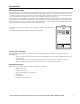
Unpack and Inspect Inspect the UTS upon receipt. Notify the carrier and dealer if there is damage. The packaging is recyclable; save it for reuse or dispose of it properly. Check the package contents: Additional contents for UTS6/UTS6H/UTS6BI All Units Additional contents for UTS10BI UTS Hardware: Hardware: UTS-to-UPS power cord • male-to-male .25 inch bypass FastOns (six) • male-to-male .25 inch bypass FastOns (ten) Site Preparation and Installation Guide • .50 in x .
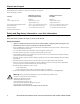
Specifications UTS Specifications UTS6/UTS6H UTS6BI UTS10BI Electrical Input - Utility Input line Voltage range Nominal voltage Rated voltage Allowable frequency Rated current Circuit: 12 AWG Neutral: 10 AWG 84 V to 142 V 120 V/240 V single phase 120 Vac 47 Hz to 63 Hz 20 A per circuit Circuit: 12 AWG Neutral: 10 AWG 84 V to 142 V 120 V/240 V single phase 120 Vac & 240 Vac 47 Hz to 63 Hz 20 A per circuit Circuit: 12 AWG Two Neutral: 10 AWG 84 V to 142 V 120 V/240 V single phase 120 Vac & 240 Vac 47 H
UTS Specifications UTS6/UTS6H UTS6BI UTS10BI Output Nominal voltage 120 V circuits Nominal voltage 240 V circuits Current per circuit Current for circuits combined Convenience outlet type Protection APC recommends that a licensed electrician replace blown fuses.
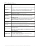
UTS Configurable Features Feature Description Uninterruptible Power • provides UPS backup for uninterrupted operation and power protection • provides backup power until the generator comes on line Supply Adaptive Load Management (ALM) Provides automatic shut off (referred to as load shedding), of select circuits during blackout conditions • prevents power surges and overload conditions from stalling a generator, or tripping circuits • increases generator efficiency by 20% or more during prolonged power
Site Planning and Preparation Select a location Select a suitable location that meets the environmental specifications and safety requirements of the UTS. Refer to the Specifications table in this manual. This unit is intended for wall mounting, either recessed into the wall for a flush mounting, or surface mounted on the wall. The unit has built in brackets for mounting. Refer to the UTS Installation section in this manual for details.
Generator Load Balance Follow these steps to ensure load balance for the generator. UTS6/UTS6BI/UTS10BI models only 1. Determine the total power rating required if all connected loads were to run continuously and simultaneously. a. Most home appliances operate for short periods of time. ALM intelligently manages the loads. Refer to the Operation Manual for a complete description of ALM functionality. b.
Surface mount installation 1. Hang the UTS on a nail using the mounting eyelet located on the rear of the unit. 2. Locate two 16 inch on center wall studs within one foot of the building circuit breaker panel. 3. Mark the wall identifying the location of the mounting tabs. 4. Secure the UTS to the wall using six screws appropriate for the UTS weight and the wall material on which the unit is being installed. 5. Proceed to the section in this manual, Connect UTS to circuit breaker panel.
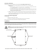
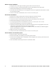
UTS circuits UTS6BI Circuit UTS6/UTS6H Circuit 1 3 5 120 V 2 1 4 3 6 120 V circuits ONLY 5 120 V 240 V UTS10BI Circuit 2 1 4 3 6 Together, circuits 5 and 6 form a dedicated 240 V circuit. DO NOT use these circuits as individual 120 V circuits. 5 2 4 120 V 8 7 9 6 240 V 10 Together, circuits 9 and 10 form a dedicated 240 V circuit. DO NOT use these circuits as individual 120 V circuits. Note: UTS6/UTS6H - Utilizing all of the UTS circuits is not necessary.
240 V circuit wiring Consult the UTS Wiring Plan table in the Quick Install Guide that was filled in previously. The UTS6 and UTS6H provide 120 V circuits only. The UTS6BI utilizes circuits 5 and 6 as a dedicated 240 V circuit. The UTS10BI utilizes circuits 9 and 10 as a dedicated 240 V circuit. 1. Locate the 240 V, 2-pole circuit breakers on the circuit breaker panel. A 2-pole circuit breaker has an interlock that forces the two circuits to open and close together. 2. Switch the circuit breakers OFF. 3.
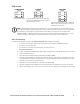
Wiring schematics UTS6 Site Preparation & Installation Guide Universal Transfer Switch UTS6 UTS6H UTS6BI UTS10BI 11
Wiring schematics UTS6H 12 Site Preparation & Installation Guide Universal Transfer Switch UTS6 UTS6H UTS6BI UTS10BI
Wiring schematics UTS6BI Site Preparation & Installation Guide Universal Transfer Switch UTS6 UTS6H UTS6BI UTS10BI 13
Wiring schematics UTS10BI 14 Site Preparation & Installation Guide Universal Transfer Switch UTS6 UTS6H UTS6BI UTS10BI
UTS Controls and Indicators The UTS controls and indicators are located on the front of the UTS.
UTS Power Connectors The power connectors are located on the front of the UTS. UTS10BI Connect Power to the UTS Verify circuit connections 1. Reconnect power to the circuit breaker panel and switch ON all of the circuit breakers. 2. Confirm the following: a. UTS6/UTS6H - confirm that the circuits supporting the UTS circuits 5 and 6 are switched ON b. UTS6BI - confirm that the 2-pole circuit supporting the UTS circuits 5 and 6 is switched ON c.
Initial Setup After several initializing LCD screens appear and the Utility Source LED illuminates, the LCD will display this message: UTS Setup Wizard STARTING UTS WIZARD ANY KEY TO CONTINUE The Setup Wizard enables the user to: • view the factory default parameter settings for the UTS • change the parameters for the UTS • reset all parameters to the factory default settings Note: The settings and values selected will change immediately after an arrow button is pressed.
Backup2 Source Type The factory default setting is UPS. The backup2 power source inlet, located on the front of the UTS is labeled UPS Inlet as a UPS is the preferred BACKUP2 power source. BACKUP2 SOURCE TYPE? UPS The system setup has three options for backup power: • Generator • UPS (recommended BACKUP2 power source) • Other Use the down/up arrow keys to select the preferred backup power source. NOTE: It is recommended that a UPS be used as BACKUP2 SOURCE TYPE.
System Status Verification The UTS system status and the status of up to three power sources can be viewed by pressing the System Status button located on the front of the UTS. To navigate through the system status menus, press the System Status button after viewing the information on the LCD. LCD displays the input voltages from the UTILITY through the main load center for PHASE1 and PHASE2.
Connect UTS to Backup Power Sources UTS10BI Generator WARNING: Home generator backup systems should be installed by a licensed electrician. Locate the generator outside a building and at least 10 feet away from buildings, windows, and doors. Failure to follow this safety rule may result in illness or death from breathing carbon monoxide. The generator must have three to four feet of space around all sides and the top to ensure proper ventilation.
UPS The UTS is equipped with a standard IEC 320, 120 V inlet specifically intended for use with a UPS. Use the power cord supplied in the accessories kit to connect the UPS to the UTS. The UTS is equipped with a standard NEMA 5-15, 120 V Convenience outlet for connecting a UPS or another selected load to the UTS. The Convenience outlet can utilize utility power or generator power, providing an uninterruptible power supply during a power outage or fluctuation.
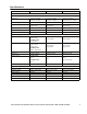
Troubleshooting Use this chart to solve minor UTS problems. Refer to www.apc.com for assistance with complex UTS problems. Problem and Possible Cause Solution Problem: The UTS conduit is too long or too short Cause: The UTS was not installed at the recommended one foot distance from the building circuit breaker panel. Conduit too long: have a licensed electrician cut the conduit to shorten the length.
Problem and Possible Cause Solution Problem: UTS configuration errors are found Cause: Initial UTS configuration is found to be incorrect. • Reset the UTS to the factory defaults and begin the setup process again. Use the System Setup button to scroll through the system setup options. Stop at RESET TO FACTORY DEFAULTS. Use the down/up arrow keys to start the Setup Wizard. Problem: A circuit is mislabeled while using the Setup Wizard Cause: An error is made while configuring the UTS circuits.
24 Site Preparation & Installation Guide Universal Transfer Switch UTS6 UTS6H UTS6BI UTS10BI Watts Power Total Power: Odd Circuits Total: Even Circuits Total: – Make/Model Seconds Overload Delay 1 Even Odd UTS Circuits Notes Normally open/closed Seconds or Minutes Start Relay 2 Stop Relay 2 Start Delay 2 Stop Delay 2 Note1 : Refer to the System Configuration and Setup section in the Operation Manual. Note2 : These entries apply only to auto start generators.
Circuit Assignments The tables on this page and the previous page are intended to be filled in and taped to the inside cover of the building circuit breaker panel enclosure. UTS6/UTS6H Circuit No. Load Description 1 2 3 4 5 6 UTS6BI Circuit No. Load Description 1 2 3 4 5/6 UTS10BI Circuit No.
Service If the unit requires service do not return it to the dealer. Follow these steps: 1. Review the problems discussed in Troubleshooting to eliminate common problems. 2. If the problem persists, contact APC Customer Support through the APC Web site, www.apc.com. – Note the model number of the unit, the serial number located on the front of the unit, and the date purchased. If you call APC Customer Support, a technician will ask you to describe the problem and attempt to solve it over the phone.
Two-Year Warranty The limited warranty provided by American Power Conversion (APC®) in this statement of Limited Factory Warranty applies only to products you purchase for your commercial or industrial use in the ordinary course of your business. Terms of warranty APC warrants its products to be free from defects in materials and workmanship for a period of two years from the date of purchase.
990-2992B 7/2008