
User's Manual UPS control system

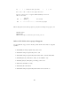


Table Of Contents
- Apcupsd User's Manual
- Release Notes
- How To Use This Manual
- Basic User's Guide
- Planning Your Installation
- Building and Installing apcupsd
- After Installation
- Configuration Examples
- Testing Apcupsd
- Troubleshooting Your Installation
- Monitoring and Tuning your UPS
- Maintaining Your UPS
- Frequently-Asked Questions
- Apcupsd Bugs
- Advanced topics
- Customizing Event Handling
- Master/Slave Configurations
- Controlling Multiple UPSes on one Machine
- Support for SNMP UPSes
- Alternate Ways To Run The Network Information Server
- apcupsd System Logging
- Installation: Windows
- Windows Version of apcupsd
- Installation: Serial-Line UPSes
- Overview of Serial-Interface UPSes
- Connecting a Serial-Line UPS to a USB Port
- Connecting a APC USB UPS to either a PC USB or Serial Port
- Cables
- Smart-Custom Cable for SmartUPSes
- Smart Signalling Cable for BackUPS CS Models
- Voltage-Signalling Cable for "dumb" UPSes
- Other APC Cables that apcupsd Supports
- Voltage Signalling Features Supported by Apcupsd for Various Cables
- Voltage Signalling
- Back-UPS Office 500 signals
- Analyses of APC Cables
- Win32 Implementation Restrictions for Simple UPSes
- Internal Apcupsd Actions for Simple Cables
- RS232 Wiring and Signal Conventions
- Pin Assignment for the Serial Port (RS-232C), 25-pin and 9-pin, Female End
- Ioctl to RS232 Correspondence
- Testing Serial-Line UPSes
- Troubleshooting Serial Line communications
- Recalibrating the UPS Runtime
- DATA Logging
- Technical Reference
- Configuration Directive Reference
- apcupsd Status Logging
- Shutown Sequence and its Discontents
- APC smart protocol
- Apcupsd --- RPM Packaging FAQ
- Credits
- Kernel Config
| B |
*-------| 2N3906 PNP
|
|\
\ C
|
|
*----< DCD (1) Low Batt
|
|
R 4.7k
3
|
4.7k |
SHUTDOWN (1) >----------*----R4----*----< TxD (3)
|
| 1N4148
*----K|---------< RTS (7) Shutdown
POWER-FAIL (2) >--------------------------< RxD,RI (2,9) On Batt
GROUND (4,9) >--------------------------< GND (5)
Operation:
* DTR is "cable power" and must be held at SPACE. DSR or CTS may be
used as a loopback input to determine if the cable is plugged in.
* DCD is the "battery low" signal to the computer. A SPACE on this
line means the battery is low. This is signalled by BATTERY-LOW
being pulled down (it is probably open circuit normally).
Normally, the transistor is turned off, and DCD is held at the MARK
voltage by TxD. When BATTERY-LOW is pulled down, the voltage
divider R2/R1 biases the transistor so that it is turned on, causing
DCD to be pulled up to the SPACE voltage.
* TxD must be held at MARK; this is the default state when no data is
being transmitted. This sets the default bias for both DCD and
SHUTDOWN. If this line is an open circuit, then when BATTERY-LOW is
signalled, SHUTDOWN will be automatically signalled; this would be
true if the cable were plugged in to the UPS and not the computer,
or if the computer were turned off.
* RTS is the "shutdown" signal from the computer. A SPACE on this
line tells the UPS to shut down.
* RxD and RI are both the "power-fail" signals to the computer. A
MARK on this line means the power has failed.
* SPACE is a positive voltage, typically +12V. MARK is a negative
voltage, typically -12V. Linux appears to translate SPACE to a 1
and MARK to a 0.
146