
User's Manual UPS control system

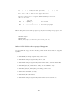


Table Of Contents
- Apcupsd User's Manual
- Release Notes
- How To Use This Manual
- Basic User's Guide
- Planning Your Installation
- Building and Installing apcupsd
- After Installation
- Configuration Examples
- Testing Apcupsd
- Troubleshooting Your Installation
- Monitoring and Tuning your UPS
- Maintaining Your UPS
- Frequently-Asked Questions
- Apcupsd Bugs
- Advanced topics
- Customizing Event Handling
- Master/Slave Configurations
- Controlling Multiple UPSes on one Machine
- Support for SNMP UPSes
- Alternate Ways To Run The Network Information Server
- apcupsd System Logging
- Installation: Windows
- Windows Version of apcupsd
- Installation: Serial-Line UPSes
- Overview of Serial-Interface UPSes
- Connecting a Serial-Line UPS to a USB Port
- Connecting a APC USB UPS to either a PC USB or Serial Port
- Cables
- Smart-Custom Cable for SmartUPSes
- Smart Signalling Cable for BackUPS CS Models
- Voltage-Signalling Cable for "dumb" UPSes
- Other APC Cables that apcupsd Supports
- Voltage Signalling Features Supported by Apcupsd for Various Cables
- Voltage Signalling
- Back-UPS Office 500 signals
- Analyses of APC Cables
- Win32 Implementation Restrictions for Simple UPSes
- Internal Apcupsd Actions for Simple Cables
- RS232 Wiring and Signal Conventions
- Pin Assignment for the Serial Port (RS-232C), 25-pin and 9-pin, Female End
- Ioctl to RS232 Correspondence
- Testing Serial-Line UPSes
- Troubleshooting Serial Line communications
- Recalibrating the UPS Runtime
- DATA Logging
- Technical Reference
- Configuration Directive Reference
- apcupsd Status Logging
- Shutown Sequence and its Discontents
- APC smart protocol
- Apcupsd --- RPM Packaging FAQ
- Credits
- Kernel Config
Note 2: the same as note 1 except that the line is normally closed,
and opens when the line voltage fails.
The Back-UPS Office 500 signals
The Back-UPS Office UPS has a telephone type jack as output, which looks
like the following:
Looking at the end of the connector:
6 5 4 3 2 1
_____________
| . . . . . . |
| |
| |----------|
|__|
It appears that the signals work as follows:
UPS Signal meaning
1 (brown) <- Shutdown when set by computer for 1-5 seconds.
2 (black) -> On battery power
3 (blue) -> Low battery
4 (red) Signal ground
5 (yellow) <- Begin signalling on other pins
6 (none) none
Analyses of APC Cables
940-0020B Cable Wiring:
This diagram is for informational purposes and is not complete. Although
we do not know what the black box semi-conductor contains, we believe that
we understand its operation (many thanks to Lazar M. Fleysher for working
this out).
This cable can only be used on voltage-signalling UPSes, and provides the
On Battery signal as well as kill UPS power. Most recent evidence (Lazar’s
143