
System information


ReplaceBoardsinInput/Output/BypassEnclosure
WARNING:Onlytrainedpersonsfamiliarwiththeconstructionandoperationof
theequipment,aswellastheelectricalandmechanicalhazardsinvolved,may
installandremovesystemcomponents.
WARNING:Beforereplacingtheboards,ensurethatthe“UPSsystemrmware
version”andthe“Systemrmwareversionstoredatmemorycard”areidenticalon
theSystemInformationscreen.
WARNING:Replaceonlyoneboardatatime.
Note:Afaultysystempowersupplycanbeidentiedviathedisplayoraashingred
LEDindication.
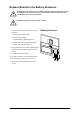
1.Loosenthetwo/fourscrewsinthecornersof
theboard.
aExternalconnectionboard.
bExternalswitchgearboard.
cSystempowersupply.
dIDandrelaycontroller.
2.Onlyapplicabletotheexternalconnection
boardandtheIDandrelaycontroller:remove
thecablesconnectedtotheboard.
3.Carefullypullouttheboard.
4.OnlyapplicabletoIDandrelaycontroller:
taketheSDmemorycardfromtheoldID
andrelaycontrollerandinstallitinthe
replacementIDandrelaycontroller.
5.Carefullyinsertthenewboardintotheslot.
6.Reconnectthecablesremovedinstep2.
7.Securethenewboardwiththetwo/four
screws.
Input/Output/BypassEnclosure
990–2748E-001
SymmetraPX250/500kW400/480V
43