
User Manual

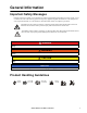
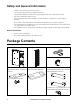
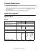
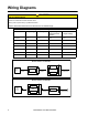
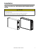
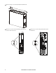
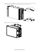
Table Of Contents
- General Information
- Important Safety Messages
- Product Handling Guidelines
- Safety and General Information
- Package Contents
- Product Description
- Product Overview
- Specifications
- Wiring Diagrams
- Installation
- Tower transformer SRT3000XLI/SRT3000XLW-IEC model
- Installing the Tower Transformer to SURT UPS
- Connection and Startup Instructions
- Tower to Rack-mount Conversion
- Transport
- Service
- Limited Factory Warranty
Smart-UPS On-Line SRT Transformer4
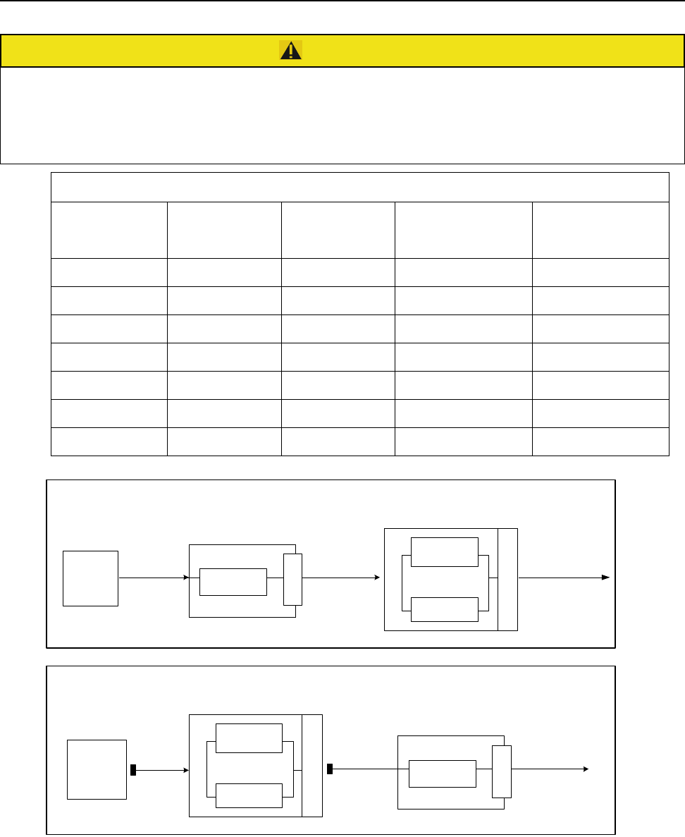
Wiring Diagrams
CAUTION
RISK OF ELECTRIC SHOCK
• Adhere to all national and local electrical codes.
• Wiring must be performed by a qualified electrician.
Failure to follow these instructions can result in minor or moderate injury.
Typical System Configuration
Model Utility Voltage UPS Output Input Voltage
Selection Switch
Position
Transformer
Output Voltage
SURT001 230 230 N/A 230
SURT002 230 230 N/A 230
SURT003 208 208 208 240/208/120
SURT003 240 240 240 240/208/120
SURT003 220 220 240 220//110
SURT004 200 200 N/A 200/100
SURT004 220 220 N/A 220/110
Models: SURT001 and SURT002
C20 or
Hardwire
3 ft Cable
L6-30 Plug
C19 or
Hardwire
AC Output to
Load Equipment
Models: SURT003 and SURT004
Utility
Souce
AC In
Utility
Souce
AC In
P
D
U
UPS
UPS
Bypass
P
D
U
Inverter
UPS
UPS
Bypass
P
D
U
Inverter
Transformer
P
D
U
Transformer
AC Output to
Load Equipment