Installation and Operation Service Bypass Panel suo0707a SBP20KP SBP20KRMT4U SBP20KRMI4U
This manual and the safety guide are available in English on the enclosed CD and the APC Web site, www.apc.com. Uživatelská příručka a bezpečnostní pokyny jsou k dispozici v češtině na přiloženém CD a na webových stránkách APC www.apc.com. Denne vejledning og sikkerhedsvejledningen er tilgængelige på dansk på den vedlagte CD og på APC's websted, www.apc.com. Dieses Handbuch sowie die Sicherheitsrichtlinien sind in deutscher Sprache auf der beiliegenden CD und auf der Website von APC unter www.apc.
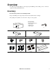
Overview The APC® by Schneider Electric service bypass panel (SBP), provides utility power to connected equipment during UPS maintenance. Inventory Read the Safety Guide before installing the UPS. Inspect the SBP upon receipt. Notify the carrier and dealer if there is damage. The package is recyclable; save it for reuse or dispose of it properly.
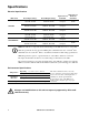
Specifications Electrical Specifications SBP model SBP20KP Rated Input Voltage Rated Output Voltage 200/208/240 VAC 50/60 Hz, 2P+PE 200/208/240 VAC 50/60 Hz, 2P+PE 125 A each phase 30,000 220/230/240 VAC 50/60 Hz 1P+N+PE 220/230/240 VAC 50/60 Hz, 1P+N+PE 125 A each phase 30,000 380/400/415 VAC 50/60 Hz, 3P+N+PE 220/230/240 VAC 50/60 Hz, 1P+N+PE 125 A each phase 30,000 200/208/240 VAC 50/60 Hz, 2P+PE 200/208/240 VAC 50/60 Hz, 2P+PE 125 A each phase 30,000 220/230/240 VAC 50/60 Hz, 1P+N+P
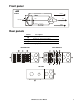
Front panel by Schneider Electric Normal Load protected Test AC Input Test Normal Bypass UPS Load not protected suo0641a Load not protected Rear panels Callout Description Equipment outlets Equipment outlet circuit breakers Utility input power hardwire access Output power hardwire access SBP20KRMI4U SBP20KRMT4U suo0686a suo0687a SBP20KP suo0688a SBP20K Series User Manual 3
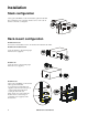
Installation Stack configuration Always place the SBP above the external battery packs and the UPS. Four ornamental screws (supplied), must be used to secure each tie bracket to the units, (see diagram). 4x suo0689a 4x Rack-mount configuration Install rails in rack For details on rail installation refer to the instructions included in the rail kit. Install rack-mount brackets suo0690a Secure the brackets to the unit using eight flat head screws (supplied).
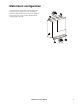
Wall-mount configuration Secure the wall-mount brackets to the unit using eight ornamental screws (supplied), four in each bracket. 4x suo0697a Secure the SBP to the wall. Select screws (not supplied), that are appropriate for the weight of the unit and the mounting surface material.
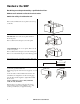
Hardwire the SBP Hardwiring must be performed by a qualified electrician. Adhere to all national and local electrical codes. Switch the utility circuit breaker off. x7 suo0702a Remove the terminal block access panel located on top of the unit. On all models, remove the access panel with three knockout pieces. suo0703a Remove all three knockout pieces from the panel. x6 Model SBP20KP has two access panels. Remove both of the access panels.
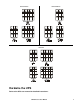
SBP20KRMI4U L2/N L1 SBP20KRMT4U N L3 L2 L1 N L3 L2 L1 L2/N L2/N L1 L2/N L1 L1 SBP20KP L2/N L1 N L3 L2 L1 L2/N L1 N L3 L2 L1 Hardwire the UPS Refer to the UPS user manual for detailed instructions.
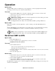
Operation Normal mode While the SBP operates in normal mode, power is supplied to connected equipment from the UPS providing protection from power variations and disturbances. Test mode 1. Switch the UPS to Bypass mode. Verify that no UPS fault conditions exist. In the event that a fault condition exists, refer to the user manuals for the UPS and SBP. 2. Switch the SBP to Test mode. Note: While the SBP is in Test mode connected equipment receives direct utility power and is not protected by the UPS.
Troubleshooting Use the table to solve minor installation and operation problems. Refer to the APC Web site, www.apc.com for assistance with complex problems. Problem and/or Possible Cause UPS will not turn on Solution SBP is in Bypass mode. Rotate the SBP switch to TEST. There is no power at the UPS input. Verify that the power cables from the SBP to the utility power, and from the SBP to the UPS input are securely connected. UPS is faulty or damaged. Rotate the SBP switch to Test.
Service If the unit requires service, do not return it to the dealer. Follow these steps: 1. Review the Troubleshooting section of the manual to eliminate common problems. 2. If the problem persists, contact APC Customer Support through the APC Web site, www.apc.com. a.Note the model number and serial number and the date of purchase. The model and serial numbers are located on the rear panel of the unit and are available through the LCD display on select models. b.
Exclusions APC shall not be liable under the warranty if its testing and examination disclose that the alleged defect in the product does not exist or was caused by end user’s or any third person’s misuse, negligence, improper installation or testing.