
Service manual


990-1008, Revision 1, 4/99 4
2. Functional Description
2.1 Functional Description
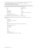
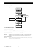
2.1.1 Block Diagram
MAINS INPUT
CONNECTIONS
BACK FEED
CONTACTOR
BOOST/BUCK
CONVERTER
BYPASS STATIC
SWITCH
MAIN INVERTERBATTERY
OUTPUT
CURRENT
SENSOR
SYSTEM OUTPUT
2.1.2 Block Diagram Description
MAINS INPUT CONNECTIONS
Function: To ensure safe and proper connection of the Smart-UPS DP.
This is the mains connection of the unit. The mains is connected via power terminals. This is
also the location of the RFI-filters, which are supplying the PSU.
BACK FEED CONTACTOR
Function: The back feed contactor ensures that there is no feedback to the mains during mains failure.
The back feed contactor is located just after the input terminals at the input connections.
BYPASS STATIC SWITCH
Function: The bypass static switch ensures switching from normal operation, battery operation, to bypass
operation without any interruptions to the load.