
Service manual
990-1008, Revision 1, 4/9943
Checked (
ä)
* Indicates steps which must always be done.
8.1.1 Check PCB’s and software revisions and updated according to EI’s
q
8.1.2 Check that fan is clean and it does not make any noise
q
8.1.3
Check stand-by voltage on batteries, (V
BATT
≥384V = 12.0V/btt.) or change
batteries.
q
8.1.4 Test Smart-UPS DP General, 7.100.542 and Step Description MPU_CAL1,
7.000.854GB.
Possibly calibrate.
In connection with changing modules pay special attention to measuring signal
on I
IN
, I
OUT
, V
BATT
, V
MAINS
, and V
OUT
as well as DC-imbalance on the output.
q
8.1.5*
Check charging voltage = 438V± 2%
q
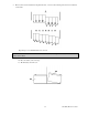
8.1.6* Check output voltage in mains operation with 100% resistive load (See App.1).
Load as much as possible, but not more than 100%.
Measure V
OUT
V
NOM
± 2%
Measure distortion on I
IN
THD max. 10 %
q
q
q
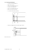
8.1.7* Check output voltage in battery operation with 100% resistive load (See
App.1).
Load as much as possible, but not more than 100%.
Measure V
OUT
V
NOM
± 2%
Measure output frequency 50/60Hz ± 0.1%
Measure distortion on V
OUT
Max. 4%
q
q
q
q
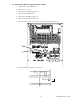
8.1.8 Check current limitation
Step 32 Enter 2 BYIH
Step 37 Enter 20 Under voltage timer
Load the system with 100% (See App. 1). Check that the system indicates
100% load (4 green LED’s are ON) and that the system is operating in normal
operation.
q
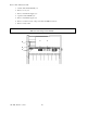
8.1.9 Load the system with 110% (See App. 1). Check that the system indicates
overload (4 red LED’s are ON) and that the system is operating in normal
operation.
q