
Service manual
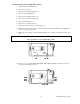

990-1008, Revision 1, 4/9931
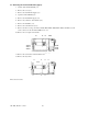
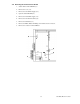
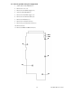
7.10 Removing the Power Unit Board 1 (Lower)
1.
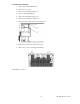
Switch off the Smart-UPS DP (7.1).
2.
Remove the cover (7.2).
3.
Remove the external DC-Supply (7.3).
4.
Open the Smart-UPS DP (7.4).
5.
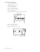
Remove the internal DC-supply (7.5).
6.
Remove the external unit cables (7.6).
7.
Remove the SmartSlot (7.7).
8.
Remove the controller board (7.8).
9.
Remove the power unit board 2 (if mounted) (7.9).
10.
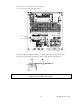
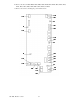
Make sure (by measuring) that there is no DC-voltage between X004 (DC 438V+) and X005 (DC
438V-) on the upper power unit.
11.
Make sure (by measuring on connector X025) that there is no voltage on electrolytes on the power
unit.
WARNING
The capacitors have a long charging time (5 min.)
;
;
;
12.
Remove wires on terminals X004, X005, X006, X022, X008, and X001, as well as the connector
for the fan shelf at X003 A, B, or C.