
Service manual

990-1008, Revision 1, 4/99 30
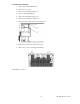
7.9 Removing the Power Unit Board 2 (Upper)
1.
Switch off the Smart-UPS DP (7.1).
2.
Remove the cover (7.2).
3.
Remove the external DC-Supply (7.3).
4.
Open the Smart-UPS DP (7.4).
5.
Remove the internal DC-supply (7.5).
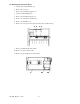
6.
Remove any cables for external units (7.6).
7.
Remove the SmartSlot (7.7).
8.
Remove the controller board (7.8).
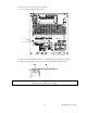
9.
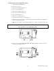
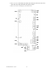
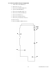
Remove the wires on the power unit terminals X004, X005, X006, X022, X008, and X001, as well
as the connector for the fan shelf at X003 A, B, or C.
10.
Remove the cover plate for heat sink.
1010x00x-008
10 10
10
X008
X006
X001
X005
X022 X004
X
003B
X
003A
X
003C
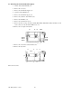
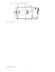
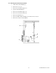
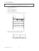
11.
Remove the screws that connect the PU-board.
12.
Remove the stay at fan.
1111
11
11
11 11 11
12
The board is now free.