
Installation Guide


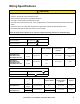

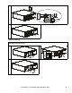

Table Of Contents
- Installation Guide Smart-UPS™On-Line SRT5K/6K Tower/Rack-Mount 3U/4U
- Safety Messages
- Product Handling Guidelines
- Safety and General Information
- FCC Class A Radio Frequency Warning
- Package Contents
- Specifications
- Remove Battery Modules
- Rack-Mount Installation
- Tower Installation
- Rear Panel Features
- Wiring Specifications
- Hardwire the UPS
- UPS Configuration
- UPS Display Interface

Smart-UPS On-Line SRT5K/6K Tower/Rack-Mount 3U/4U18
Hardwire the UPS
Input hardwiring
SRT5KRMXLW-HW
Input connections Single phase: Wire to L, L2/N,
Output connections Wire to L1, L2/N
System Wiring Voltage Current full
load, nominal
External input
circuit breaker,
(typical)
Wire size,
typical
SRT5KRMXLW-HW
Input
Output
208/220/
230/240 Vac
26 A
24 A
40 A/2-pole
6 mm
2
(8 AWG)
CAUTION
RISK OF ELECTRIC SHOCK
• Disconnect the mains input circuit breaker before installing or servicing the UPS or connected equipment.
• Disconnect internal and external batteries before installing or servicing the UPS or connected equipment.
• The UPS contains internal and external batteries that may present a shock hazard even when disconnected
from the mains.
• UPS AC hardwired and pluggable outlets may be energized by remote or automatic control at any time.
• Disconnect equipment from the UPS before servicing any equipment.
• Do not use the UPS as a safety disconnect.
• Use Snap-In strain reliefs provided with the unit.
Failure to follow these instructions can result in equipment damage and minor or moderate injury
SRT5K/6K models
Remove the 35 mm (1.38 in) knockout panels.