
Installation Guide


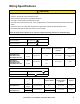

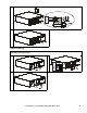

Table Of Contents
- Installation Guide Smart-UPS™On-Line SRT5K/6K Tower/Rack-Mount 3U/4U
- Safety Messages
- Product Handling Guidelines
- Safety and General Information
- FCC Class A Radio Frequency Warning
- Package Contents
- Specifications
- Remove Battery Modules
- Rack-Mount Installation
- Tower Installation
- Rear Panel Features
- Wiring Specifications
- Hardwire the UPS
- UPS Configuration
- UPS Display Interface

Smart-UPS On-Line SRT5K/6K Tower/Rack-Mount 3U/4U 17
Wiring Specifications
CAUTION
RISK OF ELECTRIC SHOCK
• Adhere to all national and local electrical codes.
• Wiring should be performed by a qualified electrician.
• Use Snap-In strain relief(s) provided with the unit.
• The UPS must be wired into a branch circuit, equipped with a circuit breaker rated as specified in the tables
below.
• Actual wire size must comply with required amp capacity and national and local electrical codes.
• Recommended input terminal screw torque: 16 lbf-in (2 Nm).
Failure to follow these instructions can result in equipment damage and minor or moderate injury
SRT5K/6KXLT/SRT5K/6KXLT-IEC models
Input connections Wire to L1, L2,
Output connections Wire to L1, L2,
System Wiring Voltage Current full
load, nominal
External input
circuit breaker,
(typical)
Wire size,
typical
SRT5KXLT
SRT5KRMXLT
SRT5KXLT-IEC
SRT 5KRM X LT-I EC
Input
Output
208/240 Vac 24 A 30 A/2-pole
L6-30
(provided with the
UPS)
SRT6KXLT
SRT6KRMXLT
SRT6KXLT-IEC
SRT 6KRM X LT-I EC
Input
Output
208/240 Vac
33 A
29 A
50 A/2-pole 6 AWG
SRT5KXLI/SRT6KXLI models
Input connections Single phase: Wire to L, N,
Output connections Wire to L, N
System Wiring Voltage Current full
load, nominal
External input
circuit breaker,
(typical)
Wire size,
typical
SRT5KXLI
SRT5KRMXLI
Input
Output
220/230/240 Vac 24 A 40 A/2-pole 6 mm
2
SRT6KXLI
SRT6KRMXLI
Input
220/230/240 Vac
30 A
50 A/2-pole 10 mm
2
Output 28 A