
Installation Manual
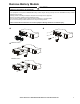


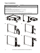
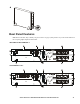
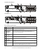
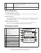
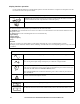
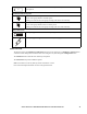
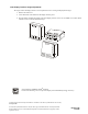
Table Of Contents
- Important Safety Messages
- Safety and General Information
- Deenergizing safety
- Electrical safety
- Battery safety
- General information
- FCC Class A radio frequency warning
- Package Contents
- Inspect the contents upon receipt. Notify the carrier and dealer if the unit is damaged.
- Specifications
- Environmental
- Physical
- Battery
- Electrical
- Remove Battery Module
- Rack-Mount Installation
- Tower Installation
- Rear Panel Features
- Key to identify rear panel features
- UPS Configuration
- Connect Emergency Power Off feature
- Verify input connection
- Configure controllable outlet groups
- UPS Display Interface
- Display interface operation
- Menu overview
- LCD display interface angle adjustment
- Select models are ENERGY STAR® qualified. For more information go to www.apc.com/company/us/en/sustainability/energy-efficiency/

Smart-UPS On-Line SRT2200XLA/SRT3000XLA Tower/Rack-Mount 2U 13
UPS Configuration
Connect Emergency Power Off feature
For instructions on how to connect the Emergency Power Off (EPO) switch, refer to the Operation and Maintenance
manual on the User Documentation CD (supplied).
Verify input connection
UPS displays Site Wiring Fault if the line and neutral connections are interchanged or if ground connection is missing.
Correct the input connections and press
OK button to clear the Site Wiring Alert. See the Config Menu UPS section in
the UPS operation manual for details.
Configure controllable outlet groups
The outlets on the UPS are grouped. To configure the controlled outlet features, use the Advanced menus on the
display interface and navigate to: Main Menu > Configuration > Outlets > Outlet Group.
UPS Display Interface
USB port
The USB port is used to connect either a server for native operating system communications,
or for software to communicate with the UPS.
Note: Serial and USB communication should not be used simultaneously. Use either the Serial
Com or the USB port.
Main outlet
Connect electronic devices to the main outlet.
POWER ON/OFF button
Button illumination indications:
-No illumination, the UPS and the output
power are off
-White illumination, the UPS and the output
power are on
-Red illumination, the UPS is on and the
output power is off
Load icon
Disable/mute audible alarm icon
UPS status information
Operation mode icons
ESCAPE button
OK button
UP/DOWN buttons
Controllable outlet group status icons
Battery status icons
su0870f
Output
120.0
v
LOAD
On-Line
12