
User manual


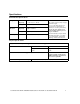
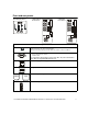
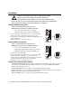
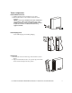
Table Of Contents
- Introduction
- Overview
- Unpack package contents
- Read the Safety Guide before installing the UPS.
- Hardware supplied
- Accessories
- Install accessories prior to connecting power to the UPS.
- Optional accessories
- Specifications
- Environmental Specifications
- Physical Specifications
- Front and rear panels
- Installation
- Output hardwire instructions
- Input hardwire instructions
- Connect the internal battery charger
- Tower configuration
- Install stabilizer brackets
- Install display panel
- Install bezel
- 2-post rack-mount configuration
- Remove and rotate display panel
- Position UPS for mounting in rack
- Install rack-mount brackets
- Secure 2-post rack to floor
- Install UPS in rack
- Install display panel
- Install bezel
- Start-up
- Connect equipment and external battery packs to UPS
- Prior to connecting the grounding cable, ensure that the UPS is NOT connected to utility or battery power.
- Start the UPS
- Operation
- Front panel display
- Display panel function buttons and indicators
- UPS function buttons
- UPS indicators
- Configuration
- UPS Settings
- Settings are adjusted through PowerChute software or optional SmartSlot accessory cards.
- Emergency Power Off (EPO)
- Connect the EPO
- External batteries
- APC battery solution
- Third party battery solution
- Connect the UPS to a battery system
- Configure UPS parameters
- Troubleshooting
- Transporting the UPS
- Prepare the UPS for transport
- Regulatory Agency Approvals and Radio Frequency Warnings
- Class A
- Service
- Contact Information
- Two-Year Warranty
User Manual Smart-UPS RC UXI/UXICH 1000/2000/3000 VA 220/230/240 Vac Tower/Rack-Mount 4U 6
Installation
Units may vary in appearance from those depicted in this manual.
Always place UPS above XLBPs in rack-mount configuration.
Connect all battery strings. Failure to do so may cause equipment damage.
Refer to Physical Specifications in this manual and the Safety Guide before installing units.
Unit is heavy. Batteries must be removed from unit prior to installation
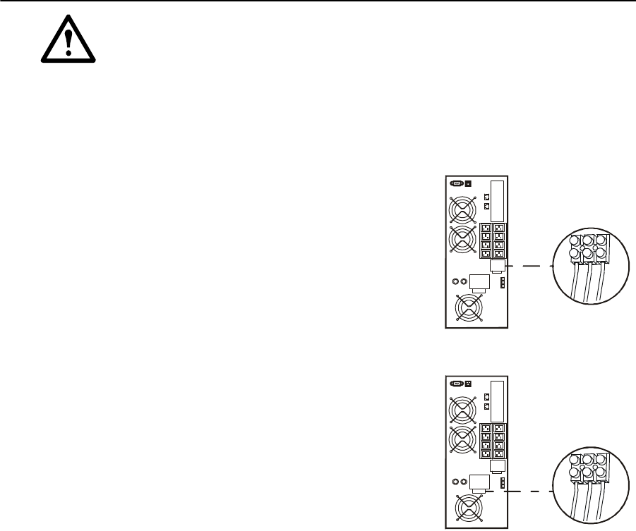
Output hardwire instructions
Adhere to all national and local electrical codes.
Wiring must be performed by a qualified electrician.
• Use 1.3 mm
2
(#16 AWG) wire (not supplied)
• Maximum output rating: 220-240 V, 50-60 Hz, 10 A
1. Locate the hardwire terminal block cover on rear panel of UPS.
Remove the screw securing the cover and remove cover.
2. Connect wires to terminal block. Terminals are labelled for proper
wire configuration.
3. Replace and secure cover removed in step 1.
Input hardwire instructions
Adhere to all national and local electrical codes.
Wiring must be performed by a qualified electrician.
• Use 3.3 mm
2
(#12 AWG) wire (not supplied)
• Install a high magnetic 30/32 A utility circuit breaker
• Maximum input rating: 220-240 V, 50-60 Hz, 25 A
1. Switch the circuit breaker OFF.
2. Locate the hardwire terminal block cover on rear panel of UPS.
Remove the screw securing the cover and remove cover.
3. Connect wires to terminal block and secure using torque 16 lb-in.
Terminals are labelled for proper wire configuration.
4. Replace and secure cover removed in step 2.
Connect the internal battery charger
2000/3000 VA UXI/UXICH models are equipped with a 600 W internal battery charger. These models can
accommodate an optional 600 W internal battery charger. To order an optional 600 W internal battery
charger contact APC at www.apc.com.
1000 VA UXI/UXICH models are equipped with a 250 W internal battery charger.
1000 VA UXI models can accommodate an optional 600 W internal battery charger. To order an optional
600 W internal battery charger contact APC at www.apc.com.
1000 VA UXICH models do not support an additional internal battery charger.
su0317a
su0318a