
User manual
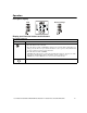
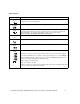
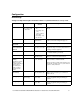
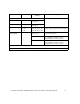
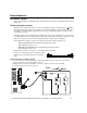
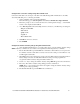
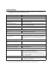
Table Of Contents
- Introduction
- Overview
- Unpack package contents
- Read the Safety Guide before installing the UPS.
- Hardware supplied
- Accessories
- Install accessories prior to connecting power to the UPS.
- Optional accessories
- Specifications
- Environmental Specifications
- Physical Specifications
- Front and rear panels
- Installation
- Output hardwire instructions
- Input hardwire instructions
- Connect the internal battery charger
- Tower configuration
- Install stabilizer brackets
- Install display panel
- Install bezel
- 2-post rack-mount configuration
- Remove and rotate display panel
- Position UPS for mounting in rack
- Install rack-mount brackets
- Secure 2-post rack to floor
- Install UPS in rack
- Install display panel
- Install bezel
- Start-up
- Connect equipment and external battery packs to UPS
- Prior to connecting the grounding cable, ensure that the UPS is NOT connected to utility or battery power.
- Start the UPS
- Operation
- Front panel display
- Display panel function buttons and indicators
- UPS function buttons
- UPS indicators
- Configuration
- UPS Settings
- Settings are adjusted through PowerChute software or optional SmartSlot accessory cards.
- Emergency Power Off (EPO)
- Connect the EPO
- External batteries
- APC battery solution
- Third party battery solution
- Connect the UPS to a battery system
- Configure UPS parameters
- Troubleshooting
- Transporting the UPS
- Prepare the UPS for transport
- Regulatory Agency Approvals and Radio Frequency Warnings
- Class A
- Service
- Contact Information
- Two-Year Warranty

User Manual Smart-UPS RC UXI/UXICH 1000/2000/3000 VA 220/230/240 Vac Tower/Rack-Mount 4U 17
Configure UPS parameters
This configuration affects the accuracy of the predicted runtime calculations the UPS performs
while running on battery power.
Refer to the Battery String Configuration tables at the end of this section for detailed instructions.
Smart-UPS RC models must be programed to recognize the number of battery strings connected to the UPS.
There are four options available for configuring the UPS to recognize the number of battery strings
1. PowerChute
®
Business Edition: Refer to the instructions included with the software
2. Network Management Card (NMC) Web interface: Refer to the instructions included with NMC
3. Network Management Card (NMC) terminal mode: Refer to the instructions below
4. UPS terminal mode
Configure UPS connection settings using NMC terminal mode
Connect the serial cable to the serial com port on rear side of UPS.
1. Open a terminal program, such as HyperTerminal
®
.
From the Desktop, go to: Start, Programs, Accessories, Communication, HyperTerminal
2. Follow the prompts to choose a name and select an icon. If the message, "...must install a
modem," click Cancel.
3. Go to File, Properties. Select the COM port that is connected to your UPS. The port settings are:
– bits per second - 2400
– data - bits 8
– parity - none
– stop bit - 1
– flow control - none
4. Click OK in each of two windows
5. Press ENTER to initiate connection to UPS.