
User manual
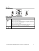
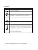
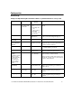
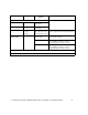
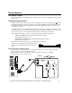
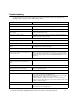
Table Of Contents
- Introduction
- Overview
- Unpack package contents
- Read the Safety Guide before installing the UPS.
- Hardware supplied
- Accessories
- Install accessories prior to connecting power to the UPS.
- Optional accessories
- Specifications
- Environmental Specifications
- Physical Specifications
- Front and rear panels
- Installation
- Output hardwire instructions
- Input hardwire instructions
- Connect the internal battery charger
- Tower configuration
- Install stabilizer brackets
- Install display panel
- Install bezel
- 2-post rack-mount configuration
- Remove and rotate display panel
- Position UPS for mounting in rack
- Install rack-mount brackets
- Secure 2-post rack to floor
- Install UPS in rack
- Install display panel
- Install bezel
- Start-up
- Connect equipment and external battery packs to UPS
- Prior to connecting the grounding cable, ensure that the UPS is NOT connected to utility or battery power.
- Start the UPS
- Operation
- Front panel display
- Display panel function buttons and indicators
- UPS function buttons
- UPS indicators
- Configuration
- UPS Settings
- Settings are adjusted through PowerChute software or optional SmartSlot accessory cards.
- Emergency Power Off (EPO)
- Connect the EPO
- External batteries
- APC battery solution
- Third party battery solution
- Connect the UPS to a battery system
- Configure UPS parameters
- Troubleshooting
- Transporting the UPS
- Prepare the UPS for transport
- Regulatory Agency Approvals and Radio Frequency Warnings
- Class A
- Service
- Contact Information
- Two-Year Warranty

User Manual Smart-UPS RC UXI/UXICH 1000/2000/3000 VA 220/230/240 Vac Tower/Rack-Mount 4U 15
Emergency Power Off (EPO)
The Emergency Power Off (EPO) option is a safety feature that will immediately remove power to all
connected equipment. When EPO button is pushed, all connected equipment will immediately turn off and
will not switch to battery power.
Adhere to all national and local electrical codes. Wiring must be performed by a qualified electrician.
The switch should be connected in a normally open switch contact. External voltage is not required; the
switch is driven by 12 V internal supply. In closed condition, 2 mA of current are drawn.
The EPO switch is internally powered by the UPS for use with non-powered switch circuit breakers.
Connect the EPO
The EPO interface is a Safety Extra Low Voltage (SELV) circuit. Connect it only to other SELV
circuits. The EPO interface monitors circuits that have no determined voltage potential. Such
closure circuits may be provided by a switch or relay properly isolated from the utility. To avoid
damage to the UPS, do not connect the EPO interface to any circuit other than a closure type circuit.
Use one of the following cable types to connect the UPS to the EPO switch.
• CL2: Class 2 cable for general use.
• CL2P: Plenum cable for use in ducts, plenums, and other spaces used for environmental air.
• CL2R: Riser cable for use in a vertical run in a floor-to-floor shaft.
• CLEX: Limited use cable for use in dwellings and for use in raceways.
• For installation in Canada: Use only CSA certified, type ELC, (extra-low voltage control cable).
• For installation in other countries: Use standard low-voltage cable in accordance with national and
local regulations.
The EPO connector is located on the rear panel of the UPS.
1. Strip insulation from one end of each wire to be used for connecting EPO.
2.
Insert a screwdriver into the slot above the terminal to be wired. Insert stripped wire into
terminal. Remove screwdriver to secure wire in terminal. Repeat for each terminal.