
User manual
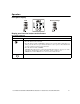
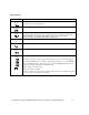
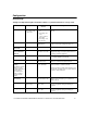
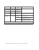
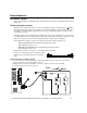
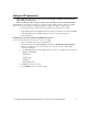
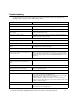
Table Of Contents
- Introduction
- Overview
- Unpack package contents
- Read the Safety Guide before installing the UPS.
- Hardware supplied
- Accessories
- Install accessories prior to connecting power to the UPS.
- Optional accessories
- Specifications
- Environmental Specifications
- Physical Specifications
- Front and rear panels
- Installation
- Output hardwire instructions
- Input hardwire instructions
- Connect the internal battery charger
- Tower configuration
- Install stabilizer brackets
- Install display panel
- Install bezel
- 2-post rack-mount configuration
- Remove and rotate display panel
- Position UPS for mounting in rack
- Install rack-mount brackets
- Secure 2-post rack to floor
- Install UPS in rack
- Install display panel
- Install bezel
- Start-up
- Connect equipment and external battery packs to UPS
- Prior to connecting the grounding cable, ensure that the UPS is NOT connected to utility or battery power.
- Start the UPS
- Operation
- Front panel display
- Display panel function buttons and indicators
- UPS function buttons
- UPS indicators
- Configuration
- UPS Settings
- Settings are adjusted through PowerChute software or optional SmartSlot accessory cards.
- Emergency Power Off (EPO)
- Connect the EPO
- External batteries
- APC battery solution
- Third party battery solution
- Connect the UPS to a battery system
- Configure UPS parameters
- Troubleshooting
- Transporting the UPS
- Prepare the UPS for transport
- Regulatory Agency Approvals and Radio Frequency Warnings
- Class A
- Service
- Contact Information
- Two-Year Warranty

User Manual Smart-UPS RC UXI/UXICH 1000/2000/3000 VA 220/230/240 Vac Tower/Rack-Mount 4U 13
Configuration
UPS Settings
Settings are adjusted through PowerChute software or optional SmartSlot accessory cards.
Function Factory Default User Selectable
Choices
Description
Automatic Self-Test On start-up and
every 14 days (336
hr) there after
• Every 7 days (168
hr)
• On start-up and
every
14 days (336 hr)
there after
• On start-up only
• No self-test
Set the interval at which the UPS will execute a
self-test.
UPS ID UPS_IDEN Up to 8 characters
(alphanumeric)
Uniquely identify UPS, (i.e. server name or
location) for network management purposes.
Date of last battery
replacement
Manufacture date mm/dd/yy Reset date when you replace the battery module.
Minimum capacity
before return from
shutdown
0% 0%, 15%, 25%, 35%,
50%, 60%, 75%, 90%
Specify percentage to which batteries will be
charged following a low battery shutdown before
powering connected equipment.
Alarm delay control Enable Enable, Mute, Disable • Mute ongoing alarms.
• Disable all alarms permanently.
Shutdown delay 20 seconds 0, 20, 60, 120, 240, 480,
720, 960 seconds
Set interval between time when UPS receives a
shutdown command and actual shutdown.
Low battery
warning
PowerChute software
interface provides
automatic, unattended
shutdown when
approximately two
minutes of battery
operated run time
remains.
2 minutes 2, 5, 7, 10, 12,
15, 18, 20 minutes
The low-battery warning beeps are continuous
when two minutes of run time remain.
Change low battery warning interval setting to the
time that the operating system or system software
requires to safely shut down.
Synchronize
turn-on delay
0 seconds 0, 20, 60, 120, 240,
480, 720, 960 seconds
Specify time UPS will wait after the return of
utility power before start up, to avoid branch
circuit overload.
High bypass point +10% of
output voltage
+5%, +10%,
+15%, +20%
Maximum voltage that UPS will pass to
connected equipment during internal bypass
operation.
Low bypass point -30% -15%, -20%,
-25%, -30%
Minimum voltage that the UPS will pass to
connected equipment during internal bypass
operation.