
User manual
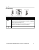
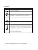
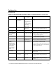
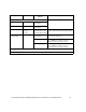
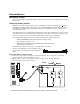
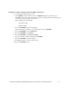
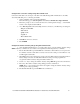
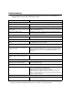
Table Of Contents
- Introduction
- Overview
- Unpack package contents
- Read the Safety Guide before installing the UPS.
- Hardware supplied
- Accessories
- Install accessories prior to connecting power to the UPS.
- Optional accessories
- Specifications
- Environmental Specifications
- Physical Specifications
- Front and rear panels
- Installation
- Output hardwire instructions
- Input hardwire instructions
- Connect the internal battery charger
- Tower configuration
- Install stabilizer brackets
- Install display panel
- Install bezel
- 2-post rack-mount configuration
- Remove and rotate display panel
- Position UPS for mounting in rack
- Install rack-mount brackets
- Secure 2-post rack to floor
- Install UPS in rack
- Install display panel
- Install bezel
- Start-up
- Connect equipment and external battery packs to UPS
- Prior to connecting the grounding cable, ensure that the UPS is NOT connected to utility or battery power.
- Start the UPS
- Operation
- Front panel display
- Display panel function buttons and indicators
- UPS function buttons
- UPS indicators
- Configuration
- UPS Settings
- Settings are adjusted through PowerChute software or optional SmartSlot accessory cards.
- Emergency Power Off (EPO)
- Connect the EPO
- External batteries
- APC battery solution
- Third party battery solution
- Connect the UPS to a battery system
- Configure UPS parameters
- Troubleshooting
- Transporting the UPS
- Prepare the UPS for transport
- Regulatory Agency Approvals and Radio Frequency Warnings
- Class A
- Service
- Contact Information
- Two-Year Warranty
User Manual Smart-UPS RC UXI/UXICH 1000/2000/3000 VA 220/230/240 Vac Tower/Rack-Mount 4U 12
UPS indicators
Indicator Description
The On Line LED illuminates when UPS is drawing utility power and performing double conversion
to supply power to connected equipment.
The UPS is supplying battery power to connected equipment.
The Bypass LED illuminates indicating that UPS is in bypass mode. Utility power is sent directly to
connected equipment during bypass mode operation. Bypass mode operation is the result of an
internal UPS fault or an overload condition. Refer to Troubleshooting in this manual.
Battery operation is not available while UPS is in bypass mode.
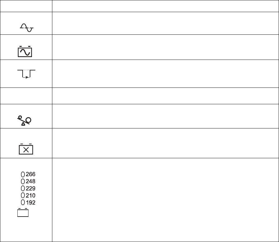
The UPS detects an internal fault. Refer to Troubleshooting in this manual.
An overload condition exists.Refer to Troubleshooting in this manual.
The battery is disconnected or must be replaced. Refer to Troubleshooting in this manual.
The UPS has a diagnostic feature that indicates utility voltage.
The UPS starts a self-test as part of this procedure. The self-test does not affect voltage display.
Press and hold the Test button to view utility voltage bar graph indicator. As soon as the On Line
LED starts flashing indicating a self-test is in progress, the five-LED Battery Charge indicator to
the right of the display panel will show utility input voltage.
Refer to diagram for voltage reading.
Values are not listed on the UPS.
Indicator on UPS shows voltage is between displayed value on list and the next higher value, Refer
to Troubleshooting in this manual for more details.
On Line
On Battery
Bypass
Fault
X
Overload
Battery
Fault
230V