Smart-UPS® RC Uninterruptible Power Supply Tower/Rack-Mount 4U UXI/UXICH SRC1000/2000/3000 VA 220/230/240 Vac English 990-3468A 09/2011
Introduction Overview The American Power Conversion (APC®) Smart-UPS® RC is a high performance uninterruptible power supply (UPS) that provides protection for electronic equipment from utility power blackouts, brownouts, sags and surges. The UPS protects electronic equipment from small utility fluctuations and large disturbances by providing continuous on-line double converted power. The UPS provides battery backup until utility power returns to safe levels or the batteries are fully discharged.
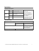
Specifications Environmental Specifications Temperature Maximum Elevation Operating 0° to 40° C (32° to 104° F) Storage -15° to 45° C (5° to 113° F) Operating 3,000 m (10,000 ft) Storage 15,000 m (50,000 ft) Humidity 0 to 95% relative humidity, non-condensing This unit is intended for indoor use only. Select a location sturdy enough to handle the weight. Do not operate UPS where there is excessive dust or temperature or humidity are outside specified limits.
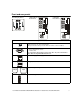
Front and rear panels UXI Model Rear Panel su0314a su0313a Test UXICH Model Rear Panel su0311a Front Display Panel Rear panel Features SRC1000UXICH model has one input circuit breaker. Other models have two input circuit breakers. The input circuit breakers protect the UPS from extreme overload conditions. Serial port for: • Power management software • Interface kits Use only interface kits supplied or approved by APC. Any other serial interface cable will be incompatible with UPS connector.
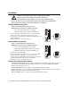
Installation Units may vary in appearance from those depicted in this manual. Always place UPS above XLBPs in rack-mount configuration. Connect all battery strings. Failure to do so may cause equipment damage. Refer to Physical Specifications in this manual and the Safety Guide before installing units. Unit is heavy. Batteries must be removed from unit prior to installation Output hardwire instructions Adhere to all national and local electrical codes. Wiring must be performed by a qualified electrician.
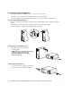
Install stabilizer brackets 1. Stabilizer brackets must be installed on tower units. 2. Each bracket must be secured with two flat head screws (supplied). NOTE: Screws are pre-installed on left side of unit. These screws must be removed from unit and used to secure stabilizer bracket. Screws for securing stabilizer bracket to right side of unit are included in hardware bag supplied with unit. su212a Tower configuration s u0 2 28 a Install display panel Locate UPS display panel in UPS packaging.
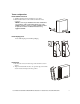
2-post rack-mount configuration This UPS is intended for installation in a 19”, two-post or four-post rack. For details on 4-post rail and rack installation refer to instructions in rail kit. Remove stabilizer brackets if they are installed. Remove four screws that secure each bracket. su0245a Remove and rotate display panel 1. To remove display panel from UPS, slide display panel up.This will disengage display panel tabs from UPS. 2.
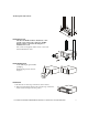
su0248a Secure 2-post rack to floor Install UPS in rack The UPS and XLBPs should be installed at or near bottom of rack. Always place UPS above XLBPs. Batteries must be removed from units prior to installation in a rack. Two screws (not supplied), must be used to secure each rack-mount bracket to rack. su0249a x2 x2 Install display panel Locate UPS display panel in UPS packaging. su0250a Install display panel as shown in diagram.
Start-up Connect equipment and external battery packs to UPS Prior to connecting the grounding cable, ensure that the UPS is NOT connected to utility or battery power. 1. Connect equipment to UPS (cables not supplied). Avoid using extension cords. 2. External battery packs provide extended runtime during power outages. This unit supports up to ten external battery packs. Refer to the APC Web site, www.apc.com for information.
Operation Front panel display Load Test su0311a Battery Charge Display panel function buttons and indicators UPS function buttons Button Test Function This button has three functions. • Press this button to turn on the UPS. • Press this button to initiate a Cold Start. Cold Start is not a normal condition. When there is no utility power and UPS is off, press and hold this button to restore power to UPS. UPS will emit two beeps. During second beep, release the button.
UPS indicators Indicator Description On Line The On Line LED illuminates when UPS is drawing utility power and performing double conversion to supply power to connected equipment. On Battery Bypass Fault The UPS is supplying battery power to connected equipment. The Bypass LED illuminates indicating that UPS is in bypass mode. Utility power is sent directly to connected equipment during bypass mode operation. Bypass mode operation is the result of an internal UPS fault or an overload condition.
Configuration UPS Settings Settings are adjusted through PowerChute software or optional SmartSlot accessory cards. Function Factory Default User Selectable Choices • Every 7 days (168 hr) • On start-up and every 14 days (336 hr) there after • On start-up only • No self-test Description Automatic Self-Test On start-up and every 14 days (336 hr) there after UPS ID UPS_IDEN Up to 8 characters (alphanumeric) Uniquely identify UPS, (i.e. server name or location) for network management purposes.
Function Factory Default User Selectable Choices Output voltage Description Allows user to select output voltage while on-line. 220 V models 220 Vac 200, 208, 220, 230, 240 Vac 230 V models 230 Vac 200, 208, 220, 230, 240 Vac Output frequency Automatic 50 ± 3 Hz 60 ± 3 Hz Automatic 50 ± 3 Hz, 50 ± 0.1 Hz, 60 ± 3 Hz, 60 ± 0.1 Hz Sets allowable UPS output frequency. Whenever possible, output frequency tracks input frequency.
Emergency Power Off (EPO) The Emergency Power Off (EPO) option is a safety feature that will immediately remove power to all connected equipment. When EPO button is pushed, all connected equipment will immediately turn off and will not switch to battery power. Adhere to all national and local electrical codes. Wiring must be performed by a qualified electrician. The switch should be connected in a normally open switch contact. External voltage is not required; the switch is driven by 12 V internal supply.
External batteries APC battery solution Refer to the APC Web site, www.apc.com or an APC dealer for information regarding the APC external battery pack. Third party battery solution Batteries must be sealed lead-acid type. Use 50 A, 250 VDC fuses with an interrupt rating of > 20,000 A. The UPS internal battery chargers are optimized only for VRLA/AGM type batteries. Do not exceed the maximum recommended battery charging current rate when configuring the amp-hour capacity of the external battery system.
Configure UPS parameters This configuration affects the accuracy of the predicted runtime calculations the UPS performs while running on battery power. Refer to the Battery String Configuration tables at the end of this section for detailed instructions. Smart-UPS RC models must be programed to recognize the number of battery strings connected to the UPS. There are four options available for configuring the UPS to recognize the number of battery strings 1.
Configure the number of battery strings using NMC terminal mode 1. Once the blank terminal window is open: 2. Press ENTER to initiate terminal mode. Press ENTER multiple times, until the prompt User Name: is displayed. Follow the prompts. Type slowly, waiting until each character appears on the screen prior to typing the next character. Network Management Card defaults: • User Name: apc • Password: apc 3. Press 1 and ENTER to select Device Manager.
Configure UPS connection settings using UPS terminal mode Connect the serial cable to the serial port on the back of the UPS. If using USB communication to the UPS, disconnect USB cable prior to connecting serial cable. 1. Open a terminal program, such as HyperTerminal From the Desktop, go to: Start, Programs, Accessories, Communication, HyperTerminal 2. Follow the prompts to choose a name and select an icon. Disregard the message, "...must install a modem," if it is displayed. Click Cancel 3.
Troubleshooting Use the table below to solve minor installation and operation problems. Refer to the APC Web site, www.apc.com for assistance with complex UPS problems. Problem and/or Possible Cause Solution UPS will not turn on The battery is not connected properly. Check that the battery connector is fully engaged. Test button not pushed. Press the Test button once to power-up the UPS and connected equipment. The UPS is not connected to utility power supply.
Problem and/or Possible Cause Solution Bypass and Fault LEDs are illuminated The UPS has automatically switched to In the event an internal UPS fault occurs, Do Not attempt to use UPS. Turn Bypass mode. Bypass mode operation is the UPS off and have it serviced immediately. Refer to APC Web site, result of an internal UPS fault or an overload www.apc.com. condition while operating on utility power.
Transporting the UPS Prepare the UPS for transport 1. 2. 3. 4. Disconnect UPS from any external batteries. Shut down and disconnect all equipment connected to UPS. Shut down and disconnect UPS from utility power. Follow shipping instructions outlined in the Service section of this manual. Regulatory Agency Approvals and Radio Frequency Warnings Class A This device complies with EN62040-2 Class A requirements. Operation is subject to the following two conditions: 1.
Service If the UPS requires service do not return it to the dealer. Follow these steps: 1. Review the problems discussed in Troubleshooting in this manual to eliminate common problems. 2. If the problem persists, contact APC Customer Support through the APC Web site, www.apc.com. a. Note the model number of the UPS, the serial number located on the rear side of the unit, and the date purchased.
Two-Year Warranty The limited warranty provided by American Power Conversion (APC®) in this statement of Limited Factory Warranty applies only to products you purchase for your commercial or industrial use in the ordinary course of your business. Terms of warranty APC warrants its products to be free from defects in materials and workmanship for a period of two years from the date of purchase.