Installation Smart-UPS® VT and MGE™ Galaxy™ 3500 Maintenance Bypass Panel with Power Distribution (wall-mount) 10-30 kVA 208 V
Contents Safety ............................................................................... 1 SAVE THESE INSTRUCTIONS . . . . . . . . . . . . . . . . . . . . . . . . . . . . . . . 1 Safety warnings . . . . . . . . . . . . . . . . . . . . . . . . . . . . . . . . . . . . . . . . . 1 Live maintenance precautions . . . . . . . . . . . . . . . . . . . . . . . . . . . . . 1 Product Overview............................................................ 3 Features . . . . . . . . . . . . . . . . . . . . . . . .
Safety SAVE THESE INSTRUCTIONS This manual contains important instructions for the Smart-UPS® VT and MGE™ Galaxy™ 3500 series that should be followed when handling the Maintenance Bypass Panel with Power Distribution (wallmount). This UL-listed unit was designed to operate in conjunction with the Smart-UPS VT and MGE Galaxy 3500 10-30kVA, 208V UPS.
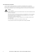
Live maintenance precautions APC does NOT recommend performing live maintenance to the MBP with Power Distribution. However, APC is aware that due to the critical nature of data center loads, live maintenance may occur. If providing live maintenance, observe the following precautions to reduce the risk of electrical shock. Caution: 1.Never work alone. 2.Only a certified electrician who is trained in the hazards of live electrical installation should perform the maintenance. 3.
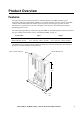
Product Overview Features The wall-mount version of the Smart-UPS VT and MGE Galaxy 3500 MBP combines bypass functionality with power distribution capability in a common enclosure.The lower section of the MBP contains switches that facilitate the transfer of power from the UPS to bypass operation to allow maintenance to be performed on the UPS. The upper section houses a 42-position panel board for distributing power to load. The unit weighs approximately 120 lbs [54.5 kg].
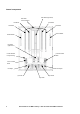
Internal components Panel Board (42-position) Neutral Bar Cable Connection Ground Bar Ground Bar Neutral Bar Neutral Bar Strain-relief Bar Strain-relief Bar Fuse Block ([3]90A Fuses) Ground Terminal Compression Lug Control Terminal Block Power Terminal Block UPS Outputs UPS Inputs Q1 Switch Q2 Switch Q3 Switch 4 Smart-UPS® VT and MGE™ Galaxy™ 3500 10-30 kVA 208 V MBP Installation
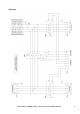
Schematic Smart-UPS® VT and MGE™ Galaxy™ 3500 10-30 kVA 208 V MBP Installation 5
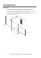
Considerations Environmental • The wall area selected for the MBP installation must be structurally sound and able to accommodate the size and weight of the unit. Refer to “Mounting the MBP” on page 9. • The MBP should be kept in a climate-controlled environment having a temperature range of 0° to 40°C [32° to 104° F] and a relative humidity of 0% to 95%, non-condensing. • The MBP must be protected at all times from excessive moisture, construction dirt, corrosive elements, and other contaminants.
Installation Overview Warning: Review “Safety” on page 1 before starting this installation. Pay strict attention to all safety warnings and caution notices! • ALL INTERNAL cable connections were made prior to shipment. • EXTERNAL cable connections with the UPS need to be made on-site. EXTERNAL cable connections from the utility also need to be made on-site. EXTERNAL cable is not supplied. • Control wire connections between the UPS and the MBP additionally need to be made on-site.
Removing the front door (optional) Note: Front door removal is NOT a requirement for this installation. However, removing the door will allow better access to the internal components. 1. Place the MBP on its back such that its front door is facing straight up. 2. Use the enclosed keys to unlock and then open the front door. 3. Disconnect the internal ground cable from the ground stud on the door. Use an M10 nut driver to remove the M6 flange nut securing the cable to the stud. 4.
Mounting the MBP APC by Schneider Electric recommends mounting the MBP to 3/4 inches plywood backing (36 in [914mm] high x 28 in [711mm] wide). 1. Attach the 3/4 inches plywood securely to the designated wall area. The wall should be strong enough to support the 120lb [54.5kg] MBP. Leave at least 18in [457mm] of space between the floor and the bottom of the plywood. Use appropriate hardware for the type of wall employed. 2. Measure and mark four (4) mounting-hole locations on the plywood backing.
Internal cable connections For the convenience of the installer, ALL internal MBP cable connections were made prior to shipment.
Making external cable connections Note: Utility cables can enter through the top or the bottom of the MBP. However, BOTTOM is recommended. External cables can enter the MBP through any of the available 1-inch [25.4mm] knockouts, or by making larger cutouts in the top or bottom plates of the enclosure. Each plate offers 22 knockouts and the ability to create up to four (4) 2-inch [50.8mm] cutouts.
UPS connections. Note: UPS cables can enter through the top or the bottom of the MBP. However, BOTTOM is recommended. Refer to the Smart-UPS VT 10-30kVA or MGE Galaxy 3500, 208V Installation Manual for MBP cable connections at the UPS. 1. Connect the four UPS inputs [L1, L2, L3, N, top-to-bottom] to the Q1 Switch in the MBP. Use a 4mm Allen wrench and torque to 60in-lbs [7Nm]. 2. Connect the four UPS outputs [L1, L2, L3, N, top-to-bottom] to the Q2 Switch in the MBP.
Re-attaching the front door Note: This section applies only if the front door was removed at the start of the installation process. If you chose not to remove the door, ignore this section. Re-attaching the front door requires at least two people: one to hold the door in place, and the other to make the necessary hardware connections. 1. Holding the door at an angle to the MBP enclosure, re-insert the three hinge clips into the three door hinges. 2.
Installing Panel Board Breakers This section describes how to install breakers to the MBP’s 42-position panel board. Electrical Hazard: Before installing breakers, make sure ALL MBP switches are in the OFF position. From normal operation, first switch Q2 OFF, and then switch Q1 OFF. 1. Use the enclosed keys to unlock and open the front door of the MBP. 2. Select the next available breaker position(s) on the panel board, and then snap the new 1-, 2-, or 3-pole breaker into the appropriate guard rail.
Appendix A: Changing Fuses Warning: Before changing fuses, make sure ALL MBP switches are in the OFF position. From normal operation, first switch Q2 OFF, and then switch Q1 OFF. Note: Replace ALL blown fuses with Bussmann “Class J” 90 Amp fuses (p/n JKS-90). Removing fuses 1. Open the front door of the MBP to access the fuse block. Use the enclosed front door keys. 2. Using a plastic or insulated fuse puller, tightly grasp the center section of the blown fuse. 3.
APC Worldwide Customer Support Customer support for this or any other APC product is available at no charge in any of the following ways: • Visit the APC Web site to access documents in the APC Knowledge Base and to submit customer support requests. – www.apc.com (Corporate Headquarters) Connect to localized APC Web sites for specific countries, each of which provides customer support information. – www.apc.com/support/ Global support searching APC Knowledge Base and using e-support.