iSCSI-SATA II SUBSYSTEM Installation Reference Guide Revision 1.
Preface About this manual This manual is the introduction of iSCSI-SATA II RAID subsystem, and to help user to know the operation of the disk array system easily. Information contained in the manual has been reviewed for accuracy, but not for product warranty because of the various environments/OS/settings, Information and specification will be changed without further notice.
Table of Contents Chapter 1 1.1 1.2 1.3 Features.............................................................................5 Terminology .......................................................................6 RAID levels ........................................................................8 Chapter 2 2.1 2.2 2.3 Front View.............................................................................................. 11 Rear View .......................................................................
3.5.5 3.6 CHAP account ....................................................................................... 37 Volume configuration.......................................................38 3.6.1 3.6.2 3.6.3 3.6.4 3.6.5 3.6.6 3.6.7 3.7 Volume relationship diagram................................................................. 38 Physical disk .......................................................................................... 39 Volume group....................................................
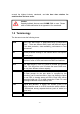
Chapter 1 RAID introduction 1.1 Features n n n n n n n n n n n n n n n n Front-end 2* 1Gb full iSCSI offload (complete ULP, TCP offload) Supports load-balancing & fail-over (802.3ad port trunking, LACP) Supports iSCSI jumbo frame Supports Microsoft Multipath I/O (MPIO) Supports RAID levels 0,1,0+1,3,5,6,10,30,50, 60 and JBOD Local N-way mirror: Extension to RAID 1 level, N copies of the disk.
exceed the highest industry standards, and the best data solution for small/medium business users. Caution Snapshot/rollback features need 512MB RAM or more. Please refer to RAM certification list in Appendix A for more detail. 1.2 Terminology The document uses the following terms: RAID RAID is the abbreviation of “Redundant Array of Independent Disks”. There are different RAID levels with different degree of the data protection, data availability, performance to host environment.
RAID width, RAID copy, RAID row (RAID cell in one row) RAID width, copy and row are used to describe one VG. E.g.: 1. One 4-disk RAID 0 volume: RAID width= 4; RAID copy=1; RAID row=1. 2. One 3-way mirroring volume: RAID width=1; RAID copy=3; RAID row=1. 3. One RAID 10 volume over 3 4-disk RAID 1 volume: RAID width=1; RAID copy=4; RAID row=3. WT Write-Through cache write policy.
WWN World Wide Name. HBA Host Bus Adapter. MPIO Multi-Path Input/Output. MC/S Multiple Connections per Session S.E.S SCSI Enclosure Services. NIC Network Interface Card. iSCSI Internet Small Computer Systems Interface. LACP Link Aggregation Control Protocol. MTU Maximum Transmission Unit. CHAP Challenge Handshake Authentication Protocol. An optional security mechanism to control access to an iSCSI storage system over the iSCSI data ports. iSNS Internet Storage Name Service. 1.
6 needs at least four hard drives. RAID 0+1 Mirroring of the member RAID 0 volumes. RAID 0+1 needs at least four hard drives. RAID 10 Striping over the member RAID 1 volumes. RAID 10 needs at least four hard drives. RAID 30 Striping over the member RAID 3 volumes. RAID 30 needs at least six hard drives. RAID 50 Striping over the member RAID 5 volumes. RAID 50 needs at least six hard drives. RAID 60 Striping over the member RAID 6 volumes. RAID 60 needs at least eight hard drives.
Chapter 2 Getting started 2.1 Before starting Before starting, prepare the following items. ¨ ¨ ¨ ¨ ¨ ¨ ¨ ¨ ¨ Check the “Certification list” in Appendix A to confirm the hardware setting is fully supported. Read the latest release notes before upgrading. Release notes accompany with release firmware. A server with a NIC or iSCSI HBA. CAT 5e, or CAT 6 network cables for management port and iSCSI data ports. Recommend CAT 6 cables for best performance. Prepare storage system configuration plan.
2.3 Identifying Parts of the subsystem The illustrations below identify the various features of the subsystem. Get yourself familiar with these terms as it will help you when you read further in the following sections. 2.3.1 Front View 1. HDD status Indicator Parts HDD Status LEDs HDD access LEDs Function Green LED indicates power is on and hard drive status is good for this slot. If hard drive defected in this slot or the hard drive is failure, the LED is orange.
2. HDD trays 1 ~ 16 (From right to left) 3. Smart Function Panel - Function Keys Parts Function Access LED Blue blinking LED indicates data is being accessed. 4. LCD display panel 5. Smart Function Panel - Function Keys for RAID configuration The smart LCD panel is where you will configure the RAID subsystem. If you are configuring the subsystem using the LCD panel, please press the controller button to configure your RAID subsystem.
2.3.2 Rear View 1. Power Supply Alarm Reset button You can push the power supply reset button to stop the power supply buzzer alarm. 2. Uninterrupted Power Supply (UPS) Port (APC Smart UPS only) The subsystem may come with an optional UPS port allowing you to connect a APC Smart UPS device. Connect the cable from the UPS device to the UPS port located at the rear of the subsystem. This will automatically allow the subsystem to use the functions and features of the UPS. 3.
6. Cooling Fan module Two blower fans are located at the rear of the subsystem. They provide sufficient airflow and heat dispersion inside the chassis. In case a fan fails to function, the ” Fan fail LED will turn red and an alarm will sound. “ 7. Power Supply Power On Indicator Green LED indicates power is on. 8. System Power On Indicator Green LED indicates power is on. 9. Power Supply Unit 1 ~ 2 Two power supplies (power supply 1 and power supply 2) are located at the rear of the subsystem.
2.4 Connecting iSCSI subsystem to Your Network To connect the iSCSI unit to the network, insert the cable that came with the unit into the network connection (LAN1) on the back of iSCSI unit. Insert the other end into a Gigabit BASE-T Ethernet connection on your network hub or switch. 2.5 Powering-on the Subsystem You should press the ON/OFF Power Supply Switch on the Switch. It will turn the iSCSI unit on and the Self-Test will be started automatically. 1.
2.6 Install Hard Drives This section describes the physical locations of the hard drives supported by the subsystem and gives instructions on installing a hard drive. The subsystem supports hot-swapping allowing you to install or replace a hard drive while the subsystem is running. 1. Pull out an empty disk tray. (You can install in any available slot.) 2. Take off the bracket before installing hard drive. 3. Place the hard drive in the disk tray. 4.
2.7 iSCSI introduction iSCSI (Internet SCSI) is a protocol which encapsulates SCSI (Small Computer System Interface) commands and data in TCP/IP packets for linking storage devices with servers over common IP infrastructures. iSCSI provides high performance SANs over standard IP networks like LAN, WAN or the Internet. IP SANs are true SANs (Storage Area Networks) which allow few of servers to attach to an infinite number of storage volumes by using iSCSI over TCP/IP networks.
The host side needs an iSCSI initiator. The initiator is a driver which handles the SCSI traffic over iSCSI. The initiator can be software or hardware (HBA). Please refer to the certification list of iSCSI HBA(s) in Appendix A. OS native initiators or other software initiators use the standard TCP/IP stack and Ethernet hardware, while iSCSI HBA(s) use their own iSCSI and TCP/IP stacks on board. Hardware iSCSI HBA(s) would provide its initiator tool. Please refer to the vendors’ HBA user manual.
browser and type the DHCP address: (The DHCP address is dynamic and user may need to check every time after reboot again.) When DHCP service is not available, IS16GL use zero config (Zeroconf) to get an IP address. E.g., on LCM. IS16GL gets a DHCP address 192.168.10.50 from DHCP server. 192.168.10.50 IS16GL ← http://192.168.10.50 or https://192.168.10.50 (https: connection with encrypted Secure Sockets Layer (SSL). Please be aware of the https function is slower than http.
Default password: 00000000 Tips SB-3164-G1A3 Series only support SSH for remote control. For using SSH, the IP address and the password is required for login. 2.9 Enclosure 2.9.1 LCM There are four buttons to control IS16GL LCM (LCD Control Module), including: (Escape), and (Enter). • (up), ‚ (down), After booting up the system, the following screen shows management port IP and model name: 192.168.10.
Reset to Default Reset to default sets password to default: 00000000, and set IP address to default as DHCP setting. Default IP address: 192.168.10.50 (DHCP) Default subnet mask: 255.255.255.0 Default gateway: 192.168.10.254 The following is LCM menu hierarchy. [Alarm Mute] [Reset/Shutdown] [Quick Install] proIPS •‚ [View IP Setting] [•Yes No‚] [Reset] [Shutdown] RAID 0 (RAID 1/RAID 3/ RAID 5/RAID 6) xxxxxx GB [IP Config] [Static IP] [IP Address] [192.168.010.050] [IP Subnet Mask] [255.255.255.
1. 2. 3. The system buzzer alarms 1 second when system boots up successfully. The system buzzer alarms continuously when there is error level event happened. The alarm will be stopped after mute. The alarm will be muted automatically when the error situation is resolved. E.g., when RAID 5 is degraded and alarm rings immediately, after user changes/adds one physical disk for rebuilding, and when the rebuilding is done, the alarm will be muted automatically.
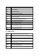
Chapter 3 Web GUI guideline 3.1 IS16GL GUI hierarchy The below table is the hierarchy of IS16GL GUI.
Upgrade Info Reset to default Config import & export Shutdown à à à à à Browse the firmware to upgrade / Export config System information Reset to factory default Controller configuration import and export function Reboot / Shutdown Logout 3.2 Login IS16GL supports graphic user interface (GUI) to operate the system. Be sure to connect the LAN cable. The default IP setting is DHCP; open the browser and enter: http://192.168.10.
1. RAID light: Green means RAID works well. Red represents RAID failure happening. 2. Temperature light: Green is normal. Red represents abnormal temperature. 3. Voltage light: Green is normal. Red represents abnormal voltage status. 4. UPS light: Green is normal. Red represents abnormal UPS status. 5. Fan light: Green is normal. Red represents abnormal fan status. 6. Power light: Green is normal. Red represents abnormal power status. 3.
E.g., user chooses RAID 5 and the controller has 12*200G HDD + 4*80HDD inserted. Then if using all 16 HDD for a RAID 5, then the volume max size is 1200G (80G*15). But in IS16GL, we do smarter check and find out the most efficient use of HDDs, which results controller only use the 200G HDD (Volume size is 200*11=2200G). Then, the volume size is bigger, and full use of HDD capacity. Step 1: Select “Quick install” then choose the RAID level to set. Please refer to ”, which Figure 3.3.1.
Figure 3.3.2 (Figure 3.3.2: A RAID 0 user data volume with the UDV name “QUICK13300”, named by the system itself, with the total available volume size 304GB.) 3.4 System configuration “System config” selection is for the setup of “System name”, “IP address”, “Login config”, “Password”, “Date”, “Mail”, “SNMP” and view “Event log”. Figure 3.4.
3.4.1 System name Select “System name” to change system name. Default system name composed by model name and serial number of this system, ex: P120-000001. Figure 3.4.1.1 3.4.2 IP address Select “IP address” to change IP address for remote administration usage. There are 2 selections, DHCP (Get IP address from DHCP server) or static IP. The default setting is DHCP enabled. User can change the HTTP, HTTPS, and SSH port number when the default port number is not allowed on host/server. Figure 3.4.2.
Figure 3.4.3.1 3.4.4 Login config Select “Login config” is to set only one admin and set the auto logout timing. The only one admin can prevent multiple users access the same controller in the same time. 1. Auto logout: Options are (1) Disable (2) 5 mins (3) 30 mins (4) 1 hour. When user is no response for a period of time, the system will logout automatically to allow another user to login. Figure 3.4.4.1 2. Login block: Disable/Enable.
3.4.6 Date Select “Date” to set up the current date, time, time zone, and NTP server before using. Figure 3.4.6.1 3.4.7 Mail Select “Mail” to enter at most 3 mail addresses for receiving the event notification. Some mail servers would check “Mail-from address” and need authentication for anti-spam. Please fill the necessary fields and select “Send test mail” to check whether the email works fine. User can also select which levels of event logs are needed to be sent out by Mail.
Figure 3.4.7.1 3.4.8 SNMP Select “SNMP” to set up SNMP trap for alert via SNMP. It allows up to 3 SNMP trap addresses. Default community setting is “public”. User can choose the event log type and the default value of SNMP is INFO event log enabled only. Figure 3.4.8.1 3.4.9 System log server Select “System log server” to set up the system log server for RAID subsystem event log trapping which is able to support remote logging.
means that event log can be forwarded from the RAID subsystem to another running syslogd which it can actually log to a disk file. Figure 3.4.9.1 1. Server IP/hostname: enter the IP address or hostname of system log server. 2. Port: enter the UDP port number on which system log server is listening to. The default port number is 514. 3. Facility: select the facility for event log. 4. Event level: Select the event log options 5. Click “Confirm” button.
4. Change controller’s system log server port number as above 5. Start logging on "Interactives Syslog Server" 3.4.10 Event log Select “Event log” to view the event messages. Press “Filter” button to choose the display. Press “Download” button will save the whole event log as text file with file name “log-ModelName-SerialNumber-Date-Time.txt” (E.g., log-IS16GLA00021-20061011-114718.txt). Press “Clear” button will clear event log. Press “Mute” button will stop alarm if system alerts. Figure 3.4.10.
Figure 3.5.1 3.5.1 Entity property Select “Entity property” to view the the entity name of the IS16GL, and setup “iSNS IP” for iSNS service. iSNS is the abbreviation of Internet Storage Name Service. Add an iSNS server IP address to the iSNS servers list which the iSCSI initiator service can send queries. Figure 3.5.1.1 3.5.2 NIC Select “NIC” to change IP addresses of iSCSI data ports. There are two gigabit LAN ports to transmit data.
(Figure 3.5.2.1: Each of iSCSI data ports is set to static IP. MTU is 1500.) ” in the User can change IP address by clicking the blue square button “ “DHCP” column. There are 2 selections, DHCP (Get IP address from DHCP server) or static IP. Figure 3.5.2.2 Default gateway can be changed by clicking the blue square button “ ” in the “Gateway” column. There is only one default gateway. The row of No. 1 would be the default gateway.
1. 2. 3. Multi-homed: The two LAN ports are connected to two different networks. Multi-homed is default. Trunking: Trunking links 2 LAN ports together to be a single link. Trunking could multiply the bandwidth. They will be aggregated to one IP. If clicking the blue square button “ ” at “No. 1” row, the IP setting will be set to default value after setting trunking, and vice versa. For detailed setup steps, please refer to Appendix E: Trunking/LACP setup instructions.
1. 2. 3. Click “ ” in Auth column. Select “CHAP”. Go to \iSCSI config\CHAP account to create account and password. Tips After setting CHAP, the initiator in host/server should be set the same Account/Password. Otherwise, user cannot login. Select “None” to disable the authentication method. 3.5.4 Session Enter “Session” function, it will display iSCSI session and connection information, including the following items: 1. Host (Initiator Name) 2. Security Protocol 3. TCP Port Number 4.
Figure 3.5.5.1 Figure 3.5.5.2 3.6 Volume configuration “Volume config” selection is for the setup of volume configurations including “Physical disk”, “Volume group”, “User data volume”, “Cache volume”, and “Logical unit” functions. Figure 3.6.1 3.6.1 Volume relationship diagram The below diagram describes the relationship of RAID components. One VG (Volume Group) consists of a set of UDVs (User Data Volume) and owns one RAID level attribute. Each VG can be divided into several UDVs.
Each UDV will be associated with one specific CV (Cache Volume) to execute the data transaction. Each CV could have different cache memory size from user’s modification/setting. LUN is the logical volume/unit, which the users could access through SCSI commands. LUN 1 UDV 1 LUN 2 LUN 3 UDV 2 Snap UDV + + + VG PD 1 3.6.2 PD 2 Dedicated CV Global CV PD 3 DS RAM Physical disk Enter “Physical disk” to view the status of hard drives inserted in the system. The following are operation tips: 1. 2. 3.
Figure 3.6.2.1 (Figure 3.6.2.1: Physical disks of slot 1, 2 are created for a VG named “VG-R0”. Physical disks of slot 3, 4, 5, 6 are created for a VG named “VG-R6”. Slot 7 is set as dedicated spare disk of VG named “VG-R6”. Slot 8 is a free disk.) · PD column description: Slot The position of hard drives. The number of slot begins from left to right at the front side. The blue square button next to the number of slot is “More Information” indication. It shows the details of the hard drive.
Status 1 “RD” à RAID Disk. This hard drive has been set to RAID. “FR” à FRee disk. This hard drive is free for use. “DS” à Dedicated Spare. This hard drive has been set to the dedicated spare of the VG. “GS” à Global Spare. This hard drive has been set to a global spare of all VGs. “RS” à ReServe. The hard drive contains the VG information but cannot be used. It may be caused by an uncompleted VG set, or hot-plug of this disk in the running time.
In this page, IS16GL also provides HDD auto spin down function to save power. The default value is disabled. User can set up in physical disk page, too. Figure 3.6.2.2 Figure 3.6.2.3 3.6.3 Volume group Enter “Volume group” to view the status of each volume group. · VG column description: Figure 3.6.3.1 (Figure 3.6.3.1: There is a RAID 0 with 2 physical disks, named “VG-R0”, total size is 76GB, free size is 46GB, related to 1 UDV. Another is a RAID 6 with 4 physical disks, named “VGR6”.) No.
the details of the volume group. Name Volume group name. The blue square button next to the Name is “Rename” function. Total(GB) Total capacity of this volume group. Free(GB) Free capacity of this volume group. #PD The number of physical disks of the volume group. #UDV The number of user data volumes related to the volume group. Status The status of volume group. “Online” à volume group is online. “Fail” à volume group is fail. · Status 1 “DG” à DeGraded mode.
3.6.4 User data volume Enter “User data volume” function to view the status of each user data volume. Figure 3.6.4.1 (Figure 3.6.4.1: Create a UDV named “UDV-01”, related to “VG-R0”, size is 30GB, status is online, write back, high priority, related to 1 LUN, with cache volume 116MB, 10GB snapshot space. The other UDV is named “UDV-02”, initializing to 23%) · UDV column description: No. Number of this user data volume. The blue square button in below to the UDV No. is “More Information” indication.
Status 1 “WT” à Write Through. “WB” à Write Back. The blue square button in below to the status1 is “Set read/write mode” function. Status 2 “HI” à HIgh priority. “MD” à MiD priority. “LO” à LOw priority. The blue square button in below to the status2 is “Set Priority” function. Status 3 “I” à user data volume is doing initializing. “R” à user data volume is doing rebuilding. Status 4 “M” à user data volume is doing migration. R% Ratio of initializing or rebuilding.
3.6.5 ATTACH LUN Attach to a LUN. SNAPSHTOT Choose a UDV to execute snapshot. CREATE Create a user data volume function. DELETE Delete a user data volume function. Cache volume Enter “Cache volume” function to view the status of cache volume. The global cache volume is a default cache volume, which is created after power on automatically, and cannot be deleted. The size of global cache is based on the RAM size. It is total memory size minus the system usage. Figure 3.6.5.
· 3.6.6 CV operations description: CREATE Create a cache volume function. DELETE Delete a cache volume function. Logical unit number Enter “Logical unit” function to view the status of attached logical unit number ”. of each UDV. User can attach LUN by clicking the “ Please refer to Figure 3.6.6.1. “Host” must input an initiator node name for access control, or fill-in wildcard “*”, which means every host can access the volume. Choose LUN and permission, then click “ ”. Please refer to Figure 3.6.6.
(Figure 3.6.6.2: UDV-01 is attached to LUN 0 with every host can access. UDV-02 is attached to LUN 1 with only initiator node named “iqn.1991-05.com.microsoft:demo” can access.) · LUN operations description: ATTACH Attach a logical unit number to a user data volume. DETACH Detach a logical unit number from a user data volume. The matching rules of access control are from top to down by sequence. For example: there are 2 rules for the same UDV, one is “*”, LUN 0; the other is “iqn.host1”, LUN 1.
1. Select “/ Volume config / Volume group”. 2. 3. “. Click “ Input a VG Name, choose a RAID level from the picklist, press 4. “ “ to choose the RAID PD slot(s), then press “ “. Check the outcome. Press “ “ if all setups are correct. Done. A VG has been created. 5. Figure 3.6.7.2 (Figure 3.6.7.2: Creating a RAID 5 with 4 physical disks, named “VG-R5”. The total size is 114GB. Because of no related UDV there, free size still remains 114GB.) Step 2: Create UDV (User Data Volume).
2. 3. 4. 5. Click “ ”. Input a UDV name, choose a VG Name and input a size to the UDV; decide the stripe high, block size, read/write mode and set priority, finally click “ “. Done. A UDV has been created. Do one more time to create another UDV. Figure 3.6.7.4 (Figure 3.6.7.4: Create UDVs named “UDV-R5-1” and “UDV-R5-2”, related to “VG-R5”, the size of “UDV-R5-1” is 50GB, the size of “UDV-R5-2” is 64GB. The status of these UDVs are online, write back, high priority with cache volume 120MB.
1. 2. 3. Select a UDV. Input “Host”, which is an initiator node name for access control, or fillin wildcard “*”, which means every host can access this volume. ”. Choose LUN and permission, then click “ Done. Figure 3.6.7.6 (Figure 3.6.7.6: UDV-R5-1 is attached to LUN 0 with any hosts can access. UDV-R5-2 is attached to LUN 1 with only initiator node named “iqn.1991-05.com.microsoft:demo” can access.) Tips The matching rules of access control are from top to down by sequence. Please refer 3.6.
Figure 3.6.7.7 (Figure 3.6.7.7: Slot 5 is set as global spare disk.) Step 5: Done. They can be used as iSCSI disks. Delete UDVs, VG, please follow the steps. Step 6: Detach LUN from UDV. In “/ Volume config / Logical unit”, Figure 3.6.7.
1. Select LUNs by clicking the checkbox of the row, then click 2. 3. “ Choose “OK”. Done. ”. There will pop up a confirm page. Step 7: Delete UDV (User Data Volume). To delete the user data volume, please follow the procedures: 1. 2. Select “/ Volume config / User data volume”. Select UDVs by clicking the checkbox of the row. 3. 4. 5. “. There will pop up a confirm page. Click “ Choose “OK”. Done. Then, the UDVs are deleted.
1. 2. Select “/ Volume config / Physical disk”. Select the global spare disk by clicking the checkbox of the row, then click “ “ to free disk. Step 10: Done, all volumes have been deleted. · Example 2 Example 2 is to create two UDVs in one VG. One UDV shares global cache volume, the other uses dedicated cache volume. First, dedicated cache volume should be created; it can be used in creating UDV. The last, delete them.
4. 5. Fill in the size and click “ “. Done. A new dedicated cache volume has been set. Tips The minimum size of global cache volume is 40MB. The minimum size of dedicated cache volume is 20MB. Step 2: Create VG (Volume Group). Please refer to Step 1 of Example 1 to create VG. Step 3: Create UDV (User Data Volume). Please refer to Step 2 of Example 1 to create UDV. To create a user data volume with dedicated cache volume, please follow the below procedures. Figure 3.6.7.10 1.
Figure 3.6.7.11 (Figure 3.6.7.11: UDV named “UDV-R5-1” uses global cache volume 40MB, and “UDV-R52” uses dedicated cache volume 20MB. “UDV-R5-2” is initializing about 5%.) Figure 3.6.7.12 (Figure 3.6.7.12: In “/ Volume config / Cache volume”, UDV named “UDV-R5-2” uses dedicated cache volume 20MB.) Step 4: Attach LUN to UDV. Please refer to Step 3 of Example 1 to attach LUN. Step 5: Set dedicated spare disk. To set dedicated spare disks, please follow the procedures: 1. 2. 3.
Figure 3.6.7.13 (Figure 3.6.7.13: Slot 5 has been set as dedicated spare disk of VG named “VG-R5”.) Step 6: Done. The PDs can be used as iSCSI disks. Delete UDVs, VG, please follow the steps. Step 7: Detach LUN from UDV. Please refer to Step 6 of Example 1 to detach LUN. Step 8: Delete UDV (User Data Volume). Please refer to Step 7 of Example 1 to delete UDV. Step 9: Delete VG (User Data Volume). Please refer to Step 8 of Example 1 to delete VG. Step 10: Free dedicated spare disk.
2. Select the dedicated spare disk by clicking the checkbox of the row, then click “ “ to free disk. Step 11: Delete dedicated cache volume. To delete the cache volume, please follow the procedures: 1. 2. Select “/ Volume config / Cache volume”. Select a CV by clicking the checkbox of the row. 3. 4. 5. “. There will pop up a confirmation page. Click “ Choose “OK”. Done. The CV has been deleted. Caution Global cache volume cannot be deleted. Step 12: Done, all volumes have been deleted. 3.
Figure 3.7.1 3.7.1 SES configuration SES represents SCSI Enclosure Services, one of the enclosure management standards. Enter “SES config” function can enable or disable the management of SES. Figure 3.7.1.1 (Figure 3.7.1.1: Enable SES in LUN 0, and can be accessed from every host.) The SES client software is available at the following web site: SANtools: http://www.santools.com/ 3.7.2 Hardware monitor Enter “Hardware monitor” function to view the information of current voltage and temperature.
Figure 3.7.2.1 If “Auto shutdown” has been checked, the system will shutdown automatically when voltage or temperature is out of the normal range. For better data protection, please check “Auto Shutdown”. For better protection and to avoid single short period of high temperature triggering Auto shutdown, IS16GL use multiple condition judgments for Auto shutdown, below is the detail of when the Auto shutdown will be triggered. 1.
S.M.A.R.T. measures many attributes of the hard drive all the time and decide the hard drives which are close to out of tolerance. The advanced notice of possible hard drive failure can allow users to back up hard drive or replace the hard drive. This is much better than hard drive crash when it is writing data or rebuilding a failed hard drive. Enter “S.M.A.R.T.” function will display S.M.A.R.T. information of hard drives. The number is the current value; the number in parenthesis is the threshold value.
Currently, the system only support and communicate with smart-UPS function of APC (American Power Conversion Corp.) UPS. Please check detail from http://www.apc.com/. First, connect the system and APC UPS via RS-232 for communication. Then set up the shutdown values when the power is gone. UPS of other vendors can work fine, but they have no such function of communication. UPS Type Select UPS Type. Choose Smart-UPS for APC, None for other vendors or no UPS.
import & export” to export and import all controller configuration except for VG/UDV setting and LUN setting, and “Shutdown” to either reboot or shutdown the system. Figure 3.8.1 3.8.1 Upgrade Enter “Upgrade” function to upgrade firmware. Please prepare new firmware file ” to select the file. named “xxxx.
When upgrading, there is a progress bar running. After finished upgrading, the system must reboot manually. Notice: When upgrading FW, IS16GL can only accept the newer version and guarantee the compatibility issue which means, if customer changes FW to older version, the VG/UDV/LUN config may be lost. 3.8.2 Info Enter “Info” function will display system type, FW number, CPU type, RAM size, and serial number. Figure 3.8.2.1 3.8.
was also imported, the user’s current data will be cleared. Below is table of available configuration in import & export function.
Physical disk spindown Not available in import function. Volume group Not available in import function. Hard disk auto spindown setting VG setting with (1) VG name, (2) size, (3) number of physical disks, (4) number of UDVs, (5) RAID level Cache volume Not available in import function. Cache volume setting with (1) size, (2) percentage User data volume Not available in import function.
Figure 3.8.5.1 3.9 Logout For security reason, “Logout” function will allow logout while no user is operating the system. Re-login the system, please enter username and password again.
Chapter 4 Advanced operation 4.1 Rebuild If one physical disk of the VG which is set as protected RAID level (e.g.: RAID 3 , RAID 5, or RAID 6) is FAILED or has been unplugged/removed, then, the VG status is changed to degraded mode, the system will search/detect spare disk to rebuild the degraded VG to a complete one. It will detect dedicated spare disk as rebuild disk first, then global spare disk. IS16GL support Auto-Rebuild function.
When rebuilding, the status of PD/VG/UDV is “R”; and “R%” in UDV will display the ratio in percentage. After complete rebuilding, “R” and “DG” will disappear. VG will become complete one. Tips The list box doesn’t exist if there is no VG or only VG of RAID 0, JBOD. Because user cannot set dedicated spare disk for these RAID levels. Sometimes, rebuild is called recover; these two have the same meaning. The following table is the relationship between RAID levels and rebuild. RAID 0 Disk striping.
RAID 50 Striping over the member RAID 5 volumes. RAID 50 allows two hard drives fails or unplugging, but at different arrays. RAID 60 Striping over the member RAID 6 volumes. RAID 40 allows four hard drives fails or unplugging, but each two at different arrays. JBOD The abbreviation of “Just a Bunch Of Disks”. No protection of data. VG fails if any hard drive fails or unplugs. 4.2 VG migration and expansion To migrate the RAID level, please follow the below procedures.
Figure 4.2.1 Figure 4.2.2 (Figure 4.2.2: A RAID 0 with 2 physical disks migrates to RAID 5 with 3 physical disks.) Figure 4.2.3 (Figure 4.2.3: A RAID 0 migrates to RAID 5, complete percentage is 12%.
Tips To do migration/expansion, the total size of VG must be larger or equal to the original VG. It does not allow expanding the same RAID level with the same hard disks of original VG. During setting migration, if user doesn’t setup correctly, controller will pop up warning messages. Below is the detail of messages. "Invalid VG ID": Source VG is invalid. "Degrade VG not allowed": Source VG is degraded. "Initializing/rebuilding operation's going": Source VG is initializing or rebuilding.
Figure 4.3.1 Figure 4.3.2 (Figure 4.3.2: Extend UDV-R0 from 5GB to 10GB.) Tips The size of UDV extension must be larger than original. Caution UDV Extension cannot be executed during rebuild or migration. 4.4 Snapshot /Rollback IS16GL Snapshot-on-the-box captures the instant state of data in the target volume in a logical sense. The underlying logic is Copy-on-Write -- moving out the to-be-written data to certain location whenever a write action occurs since the time of data capture.
unfortunate reason it might be (e.g. virus attack, data corruption, human errors and so on). Snap UDV is allocated within the same VG in which the snapshot is taken, we suggest to reserve 20% of VG size or more for snapshot space. Please refer to Figure 4.4.1 for snapshot concept. Figure 4.4.1 Caution Snapshot /rollback features need 512MB RAM at least. Please also refer to RAM certification list in Appendix A. 4.4.1 Create snapshot volume To take a snapshot of the data, please follow the procedures.
4. 5. 6. 7. These numbers mean “Free snapshot space” and “Total snapshot space”. Choose a UDV by clicking the checkbox of the row and then click “ ”. A snapshot UDV is created with the date and time taken snapshot of the chosen UDV. The snapshot UDV size is the same as the chosen UDV no matter the actual snapshot UDV data occupies. Attach LUN to UDV, please refer to section 3.6.6 Logical unit number for more detail. Done. It can be used as a disk. Figure 4.4.1.1 (Figure 4.4.1.1: No.1 is a RAID 0 UDV.
4.4.2 Auto snapshot The snapshot copies can be taken manually or by schedule such as hourly or daily. Please follow the procedures. 1. 2. 3. 4. 5. Select “/ Volume config / User data volume”. Create a snapshot space. Please refer to section 4.4.1 for more detail. ” in “Snapshot (GB)” column to set auto snapshot . Click “ The auto snapshot can be set at the period of monthly, weekly, daily, or hourly. Done. It will take snapshots automatically. Figure 4.4.2.1 (Figure 4.4.2.
4.4.3 Rollback The data in snapshot UDV can rollback to original UDV. Please follow the procedures. 1. 2. 3. Select “/ Volume config / User data volume”. Take one or more snapshots. Please refer to section 4.4.1 for more detail. ” in “Snapshot (GB)” column to rollback the data, which Click “ user can recover data to the time that snapshot is taken. Rollback function has some constraints as described in the following: 1. 2. 3. 4. Minimum RAM size of enabling rollback function is 512MB.
capacity needs to be greater or equal to the source capacity. (The target UDV capacity is equal or larger than the source UDV capacity.) To do a QCopy task, please follow the below steps: 1. 2. 3. 4. 5. 6. 7. 8. 9. Take snapshot on the source UDV, for detail setup steps of snapshot, please refer to section 4.4.1. When setup UDV block size, please set 512B for the block size. The QCopy now supports 512B block size only.
Figure 4.5.1 (Figure 4.5.1: setup QCopy on selected snapshot UDV) Figure 4.5.2 (Figure 4.5.2: input the target system data port IP address) Figure 4.5.3 (Figure 4.5.3: select the target UDV LUN, the target UDV capacity must be equal or larger than the source UDV capacity.) Figure 4.5.4 (Figure 4.5.4: click OK after the target UDV is dismounted from host/server.) Figure 4.5.5 (Figure 4.5.
Caution Before executing QCopy, it is better to dismount target file system for avoiding any inconsistent data IO. SB-3164-G1A3 controller also send pop-up message when user checks QCopy function.
4.6 Disk roaming Physical disks can be re-sequenced in the same system or move whole physical disks from system-1 to system-2. This is called disk roaming. Disk roaming has some constraints as described in the following: 1. 2. Check the firmware of two systems first. It’s better that both have same firmware version or newer. Whole physical disks of related VG should be moved from system-1 to system-2 together.
Appendix A. Certification list · RAM RAM Spec: 184pins, DDR333(PC2700), Reg.(register) or UB(Unbufferred), ECC or Non-ECC, from 64MB to 1GB, 32-bit or 64-bit data bus width, x8 or x16 devices, 9 to 11 bits column address.
System Requirements: Mac® OS X v10.3.5 or later For ATTO initiator, it is not free. Please contact your local distributor for ATTO initiator. Tips Please check “OS_HBA_Initiator List.pdf” for the latest update and detail information of iSCSI initiator.
· SATA hard drive Vendor Model Hitachi Hitachi Hitachi Hitachi Maxtor Maxtor Samsung Seagate Seagate Seagate Seagate Seagate Seagate Western Digital Western Digital Western Digital Western Digital Deskstar 7K250, HDS722580VLSA80, 80GB, 7200RPM, SATA, 8M Deskstar 7K80, HDS728080PLA380, 80GB, 7200RPM, SATA-II, 8M Deskstar 7K500, HDS725050KLA360, 500G, 7200RPM, SATA-II, 16M Deskstar 7K80, HDS728040PLA320, 40G, 7200RPM, SATA-II, 2M DiamondMax Plus 9, 6Y080M0, 80G, 7200RPM, SATA, 8M DiamondMax 11, 6H500F0, 5
Info Error Error Warning · Warning Warning Warning Warning Type Disk error Disk error HDD failure Channel error Description Error: Disk read block error. Error: Disk writes block error. Error: Disk is failed. Error: Disk IO incomplete. SES events Level Info Warning Info Info · Info: Non-ECC Memory is installed. Error: Host channel chip failed. Error: Drive channel chip failed. Warning: GUI Ethernet port failed.
Warning Voltage warning Info Error Info Error Error Error Info Warning Error Error PSU restore PSU Fail Fan restore Fan Fail Fan non-exist AC Loss UPS Detection OK UPS Detection Fail AC Loss UPS power low Info Mgmt Lan Port Active Mgmt Lan Port Failed RTC Device OK RTC Access Failed Reset Password Reset IP Warning Info Warning Info Info · Info Info Error Warning Type Sys Config.
Warning Info Info Warning Info Info Warning Info Warning VG Created Fail VG Deleted UDV Created OK UDV Created Fail UDV Deleted UDV Attached OK UDV Attached Fail UDV Detached OK UDV Detached Fail Info UDV_OP Rebuild Started UDV_OP Rebuild Finished UDV_OP Rebuild Fail UDV_OP Migrate Started UDV_OP Migrate Finished UDV_OP Migrate Failed VG Degraded UDV Degraded Info Warning Info Info Warning Warning Warning Info Warning Warning Warning Warning Warning UDV Init OK UDV_OP Stop Initialization UDV IO Fault
Error Error Error Info · read/write error PD read/write error UDV recoverable read/write error UDV unrecoverable read/write error UDV stripe rewrite start/fail/succeed Snapshot events Level Warning Type Info Allocate Snapshot Mem Failed Allocate Snapshot Space Failed Reach Snapshot Threshold Snapshot Delete Info Snapshot replaced Info Info Take a Snapshot Set Size for Snapshot Snapshot rollback start Snapshot rollback finish Warning Warning Info Info · failed.
1. Microsoft MPIO is not supported on Windows XP or Windows 2000 Professional. Workaround solution: Using Windows Server 2003 or Windows 2000 server to run MPIO. D. Microsoft iSCSI Initiator Here is the step by step to setup Microsoft iSCSI Initiator. Please visit Microsoft website for latest iSCSI initiator. The following setup may not use the latest Microsoft iSCSI initiator. 1. 2. Run Microsoft iSCSI Initiator version 2.03. Please see Figure D.1. Click “Discovery”. Figure D.1 3. Click “Add”.
4. Click “OK”. Please see Figure D.3. Figure D.3 5. Click “Targets”. Please see Figure D.4. Figure D.4 6. Click “Log On”. Please see Figure D.5. Check “Enable multi-path” if running MPIO.
Figure D.5 7. Click “Advance” if CHAP information is needed. Please see Figure D.6. Figure D.6 8. 9. Click “OK”. The status would be “Connected”. Please see Figure D.7. Done, it can connect to an iSCSI disk.
Figure D.7 The following procedure is to log off iSCSI device. A. Click “Details”. Please see Figure D.8. Figure D.8 B. C. D. Check the Identifier, which will be deleted. Click “Log off”. Done, the iSCSI device log off successfully.
E. Trunking/LACP setup instructions Here is the step by step to setup Trunking and LACP. There are 2 kinds of scenarios for Trunking/LACP. Please see Figure E.1. Figure E.1 Network diagram of Trunking/LACP. The setup instructions are in the following figures. ž Create a VG with RAID 5, using 3 HDDs. Figure E.
ž Create a UDV by using the RAID 5 VG. Figure E.3 ž Run Microsoft iSCSI initiator 2.03 and check the Initiator Node Name. Figure E.4 ž Attaching LUN to R5 UDV. Input the Initiator Node Name in the Host field.
Figure E.5 ž Done, please check the settings. Figure E.6 ž Check iSCSI settings. The IP address of iSCSI data port 1 is 192.168.11.229. Using port 1 as Trunking or LACP. Click the blue square in “Aggregation” field to set Trunking or LACP. Figure E.7 ž Select “Trunking”. If LACP is needed, please see Figure E.12. Figure E.
ž Now, the setting is in Trunking mode. Figure E.9 ž Enable switch Trunking function of port 21 and 23. Below is an example of Dell PowerConnect 5324. Go to Figure E.14 for next step. Figure E.10 ž Select “LACP”. If Trunking is needed, please see Figure E.8. Figure E.
ž Now, the setting is LACP mode. Figure E.12 ž Enable switch LACP function of port 21 and 23. Below is an example of Dell PowerConnect 5324. Figure E.13 ž Add Target Portals in Microsoft iSCSI initiator 2.03.
Figure E.14 ž Input the IP address of iSCSI data port 1 (192.168.11.229 as mentioned in previous page). Figure E.15 ž Click “Targets” to log on.
Figure E.16 ž Log on. Figure E.17 ž Click “Advanced”.
Figure E.18 ž Select Target Portal to iSCSI data port 1 (192.168.11.229). Then click “OK”. Figure E.19 ž The setting is completed.
Figure E.20 ž Run “Computer Management” in Windows. Make sure the disks are available. Then the disks can be tested for performance by IOMETER. Figure E.
F. MPIO and MC/S setup instructions Here is the step by step to setup MPIO. There are 2 kinds of scenarios for MPIO. Please see Figure F.1. IS16GL suggests using scenario 2 for better performance. ž Network diagram of MPIO. Figure F.1 The setup instructions are in the following figures. ž Create a VG with RAID 5, using 3 HDDs. Figure F.2 ž Create a UDV by using RAID 5 VG.
Figure F.3 ž Run Microsoft iSCSI initiator 2.03 and check the Initiator Node Name. Figure F.4 ž Attaching LUN to R5 UDV. Input the Initiator Node Name in Host field. Figure F.5 ž The volume config setting is done.
Figure F.6 ž Check iSCSI settings. The IP address of iSCSI data port 1 is 192.168.11.229, port 2 is 192.168.12.229 for example. Figure F.7 ž Add Target Portals on Microsoft iSCSI initiator 2.03. Figure F.8 ž Input the IP address of iSCSI data port 1 (192.168.11.229 as mentioned in previous page).
Figure F.9 ž Add second Target Portals on Microsoft iSCSI initiator 2.03. Figure F.10 ž Input the IP address of iSCSI data port 2 (192.168.12.229 as mentioned in previous page).
Figure F.11 ž The initiator setting is done. Figure F.12 ž Log on.
Figure F.13 ž Enable “Enable multi-path” checkbox. Then click “Advanced”. Figure F.14 ž Select Target Portal to iSCSI data port 1 (192.168.11.229).
Figure F.15 ž Log on again. Figure F.16 ž Enable “Enable multi-path” checkbox. Then click “Advanced”.
Figure F.17 ž Select Target Portal to iSCSI data port 2 (192.168.12.229). Then select “OK” Figure F.18 ž iSCSI device is connected. Click “Details”.
Figure F.19 ž Click “Device” tab, then click “Advanced”. Figure F.20 ž Click “MPIO” tab, select “Load Balance Policy” to “Round Robin”.
Figure F.21 ž Click “Apply”. Figure F.22 ž Run “Device Manage” in Windows. Make sure MPIO device is available. Then the disk can be tested performance by IOMETER.
Figure F.23 The MC/S setup instructions are very similar to MPIO, detail steps are in the following figures. For the target side setting, the steps are exactly the same as MPIO. Please refer to Figure F.1 to Figure F.9. ž Create a VG with RAID 5, using 3 HDDs. ž Create a UDV by using RAID 5 VG. ž Run Microsoft iSCSI initiator 2.03 and check the Initiator Node Name. ž Attaching LUN to R5 UDV. Input the Initiator Node Name in Host field. ž The volume config setting is done. ž Check iSCSI settings.
Figure F.24 ž Log on. Figure F.25 ž Then click “Advanced”.
Figure F.26 ž Select set Local Adapter, Source IP, and Target Portal to iSCSI data port 1 (192.168.11.229). Then click “OK” Figure F.
Figure F.28 ž Choose “Round Robin” for Load Balance Policy Figure F.29 ž “Add” Source Portal for the iSCSI data port 2(192.168.12.
Figure F.30 Figure F.31 ž Select Local adapter, Source IP, and Target Portal to iSCSI data port 2 (192.168.12.229).
Figure F.32 ž The MC/S setting is done. G. QLogic QLA4010C setup instructions The following is the step by step setup of Qlogic QLA4010C. ž Log on the iSCSI HBA Manager and the current state shows “No Connection Active”.
Figure G.1 ž Click “Target settings”. Then select the target and click “Config Parameters”. Figure G.
ž Disable “Immediate Data” and enable “Initial R2T”. Figure G.3 ž Click “OK”. Figure G.4 n Click “Save settings” and click “Yes” on next page.
Figure G.5 ž Click “Refresh” and find a new target with iSCSI name. Figure G.6 ž Check the parameters which “Initial R2T” are enabled.
Figure G.7 ž Check “Target Information” again and the state changed to “Session Active”. Figure G.8 ž Then, run “Computer Management” in Windows. Make sure the disk appears.
Figure G.9 H. Installation Steps for Large Volume (TB) Introduction: IS16GL are capable to support large volumes (>2TB) on all product lines. When connecting IS16GL to 64bit OS installed host/server, the host/server is inherently capable for large volumes from the 64bit address.
7. 8. 9. Gigabit LAN switches. (Recommended) or Gigabit LAN switches with VLAN/LACP/Trunking functions. (Optional) CHAP security information, including CHAP usernames and secrets. (Optional) Setup the hardware connection before power up servers and IS16GL. Connect console cable, management port cable, SCSI cables, terminators, and iSCSI data port cables first. Step A: configure your target 1. Go to \Volume config\Volume group, create a VG. Figure H.1: create VG. Figure H.2: choose RAID level and disks.
Figure H.4: a RAID 6 (size 2793G) VG is created. 2. Go to \Volume config\User data volume, create a UDV Figure H.5: create UDV. Figure H.6: setup capacity, stripe height, and block size for UDV. Notice: When the OS is 64bit, user can set the block size to any available value. If the OS is 32bit, user has to change the block size to larger values than 512B. There will be a confirmation pop-up when UDV size is over 2TB for reminding. Figure H.
Figure H.8: a 2793G UDV is created. You may want to check the detail information of this UDV, go to click No. 1 icon. Figure H.9: block size = 512B, for 64bit OS setting. Figure H.10: block size = 4K, for 32bit OS setting. Figure H.11: attach LUN for iSCSI controller.
Figure H.12: attach LUN. Step B: configure your host/server 1. User needs to setup software iSCSI initiator or iSCSI HBA first. 2. Below is the configuration for Windows Server 2003 R2 with Microsoft iSCSI initiator. Please install the latest Microsoft iSCSI initiator from below link. http://www.microsoft.com/downloads/details.aspx?FamilyID=12cb3c1a-15d64585-b385-befd1319f825&DisplayLang=en Figure H.13: run MS iSCSI initiator, go to “Discovery” tab, add target portal (iSCSI data port).
Figure H.14: go to “Targets” tab, click “Refresh”, and then “Log On…” the target. Figure H.15: Status is “Connected”, the initiator setting is done. Step C: Initialize/Format/Mount the disk 1.
Figure H.16: Disk drive status of IS16GL 2. Go to Control Panel \Computer Management\Disk Management Figure H.17: New Disk! Figure H.18: Initialize disk.
Figure H.19: Convert to GPT Disk for over 2TB capacity. For more detail about GPT, please visit http://www.microsoft.com/whdc/device/storage/GPT_FAQ.mspx. Figure H.20: format disk. Figure H.21: format is done.
Figure H.22: the new disk is ready to go, available size = 2.72TB. Notice: if user setup 512B block size for UDV and the host/server OS is 32bit, in the last step of formatting disk, user will find OS cannot format the area after 2048GB (2TB). Figure H.
System information SW version IS16GL 2.2.