User’s Manual Rack LCD Console KVM Switch AP5808 AP5816
This manual is available in English on the enclosed CD. Dieses Handbuch ist in Deutsch auf der beiliegenden CD-ROM verfügbar. Este manual está disponible en español en el CD-ROM adjunto. Ce manuel est disponible en français sur le CD-ROM ci-inclus. Данное руководство на русском языке имеется на прилагаемом компакт-диске. 您可以从包含的 CD 上获得本手册的中文版本。 동봉된 CD 안에 한국어 매뉴얼이 있습니다 .
Contents General Information ........................................................ 1 Overview . . . . . . . . . . . . . . . . . . . . . . . . . . . . . . . . . . . . . . . . . . . . . . . . 1 Symbols used in this manual . . . . . . . . . . . . . . . . . . . . . . . . . . . . . . 1 Cross-reference symbol used in this manual . . . . . . . . . . . . . . . . . 1 Safety . . . . . . . . . . . . . . . . . . . . . . . . . . . . . . . . . . . . . . . . . . . . . . . . . . . 2 Components . . . . . . . . . . . . .
Keyboard Port Operation . . . . . . . . . . . . . . . . . . . . . . . . . . . . . . . . . . 18 Hotkey Port Control . . . . . . . . . . . . . . . . . . . . . . . . . . . . . . . . . . . . . . 18 Invoke Hotkey Mode . . . . . . . . . . . . . . . . . . . . . . . . . . . . . . . . . . . . . 18 Selecting the Active Port . . . . . . . . . . . . . . . . . . . . . . . . . . . . . . . . . 19 Auto Scan Mode . . . . . . . . . . . . . . . . . . . . . . . . . . . . . . . . . . . . . . . . 19 Skip Mode . . . . . . . . . .
General Information Overview Note the definitions for the icons here and be observant for them throughout this manual. They are intended to call attention to potential hazards and important information. Symbols used in this manual Electrical Hazard: Indicates an electrical hazard which, if not avoided, could result in injury or death. Warning: Indicates a hazard which, if not avoided, could result in personal injury or death.
Safety Read and adhere to the following important safety considerations when working with the Integrated Analog KVM (Keyboard, Video, Monitor Switch) Rack LCD (Liquid Crystal Diode Monitor). Note: 1. Read all of the instructions. Follow all warnings and instructions. 2. All work must be performed by American Power Conversion (APC®) authorized personnel only. Electrical Hazard: 1. If you are not sure if your power source is compatible with the device requirements, consult your electrician or power company.
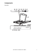
Components Front View EXIT MENU LCD POWER UPGRADE FW UPGRADE Stand by NORMAL RECOVERY 2 3 4 5 6 7 8 9 10 11 12 13 14 15 16 NUM LOCK PORT ID DOWN UP STATION ID DOWN UP Rack LCD Console KVM Switch User’s Manual CAPS LOCK SCROLL LOCK RESET aem0344b 1 3
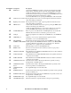
Item Number Component 4 Description EXIT button Left/Down Arrows button Pressing this button moves left or down through the menu and decreases the value when making an adjustment. Right/Up Arrows button Pressing this button moves right or up through the menu and increases the value when making an adjustment. MENU button 1. If the OSD user interface has not been opened, pressing the MENU button initiates it and brings up the Main menu. 2.
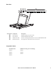
Rear View 1 CHAIN OUT 8 7 6 5 4 3 2 1 0 aem0345a POWER Item Number Component Description Power Socket Standard 3-prong AC power socket. Power Switch Standard ON/OFF rocker switch CHAIN OUT Port Port for connecting KVM stations in series to the KVM Rack LCD KVM Port Section The plugs for the cables that connect to the servers.
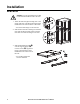
Installation Brackets Caution: Use only the hardware provided to install the KVM Rack LCD in the rack. 1. Attach the left and right mounting rails to the inside of the rack. The flange that supports the KVM Rack LCD station will be to the inside. – Screw the front flanges to the rack first. na0347a 2. Slide the bars with the rear flanges toward the rack until the flanges make contact with the rack then screw the rear flanges to the rack. 3. Slide the KVM Rack LCD () onto the support flanges ().
4. Slide the rear attachment sliding brackets along the slide bars until they contact the rear of the KVM Rack LCD. Use the supplied screws to attach the bars to the rear of the KVM Rack LCD switch. Fully tighten these screws. 5. Slide the KVM Rack LCD open and closed two or three times to be sure it is operating smoothly. aem0348a 6. If the KVM Rack LCD is moving properly in the brackets, fully tighten the screws inserted in step 3.
Multiple KVM Switches Installed in Series Note: 1. Only APC KVM switches (AP5201 and AP5202) are recommended for use with the APC KVM Rack LCD. For more information, refer to the KVM switch manuals. Note: 2. The distance between any two KVM switches in the series cannot exceed 15 meters. Note: 3. The distance between the KVM Rack LCD and the last KVM switch in the series cannot exceed 100 meters (328 ft). Installation Up to 31 KVM switches can be cascaded from your KVM Rack LCD. 1.
Operation Basic Functions Opening the KVM Rack LCD To access the console, slide the KVM Rack LCD out of the rack and raise the cover. Caution: Do not lean your body weight on the keyboard. Do not place heavy objects on the keyboard. Closing the KVM Rack LCD Close the cover and slide the KVM Rack LCD back into the rack. Powering off and restarting 1. Place the power switch on the back of the KVM Rack LCD in the OFF position to remove power. 2. Unplug the KVM Rack LCD or KVM switch from its power source. 3.
Monitor settings Setting Explanation Brightness Adjust the brightness level of the screen. Contrast Adjust level of color difference between foreground and background colors. Phase Adjust the phase setting of the screen so that no dark horizontal bands are visible. Clock Adjust the clock setting of the screen so that no dark vertical bands are visible. H-Position Moves the display area left or right. V-Position Moves the display area up or down.
Port ID Numbering Each KVM port in the installation is assigned a unique Port ID. The Port ID is made up of the Station Number and the Port Number. Example: A server attached to Port 6 of Station 12 has a Port ID of 12-06. • The Station Number is a two digit number that signifies the position of the KVM Rack LCD or a KVM station in the series. This number is displayed on the Station ID LED display of the KVM Rack LCD. See “STATION ID LED display” on page 4 for more information.
OSD Main Screen 1. The User main screen does not show the F4 and F6 functions, since these are reserved for the Administrator and can’t be accessed by users. 2. The OSD always starts in the list view, with the highlight bar at the same position it was in the last time it was closed. 3. Only ports accessible for the current logged in user are visible. The administrator sets accessibility. See “SET ACCESSIBLE PORTS” on page 15 for more information. 4.
F1: GOTO. Click on the F1 field or press the F1 key to activate the GOTO function. GOTO allows you to switch directly to a port by entering the name of the port or the Port ID. • Name method: enter the number 1, the name of the port, then press the Enter key. • Port ID method: enter the number 2, the Port ID, then press the Enter key. Note: A partial name or Port ID can be entered. All servers (that the user has View rights to) that match the pattern entered will be shown on the screen.
Setting Function PORT ID DISPLAY MODE Selects how the port ID is displayed: the port number plus the port name (PORT NUMBER + PORT NAME) (default); the port number alone (PORT NUMBER); or the port name alone (PORT NAME). SCAN DURATION Determines how long the focus dwells on each port as it cycles through the selected ports in Auto Scan mode (see “F7: SCAN” on page 17). Key in a value from 1-255 seconds, then press the Enter key. Default is 5 seconds; a setting of 0 disables the SCAN function.
F4: ADM. Allows the administrator only to configure and control the overall operation of the OSD. 1. To change a setting, double-click or use the up and down arrow keys to move the highlight bar to the selection and then press the Enter key. 2. A submenu with further choices appears following item selection. Double-click or move the highlight bar to the submenu item, then press Enter. An icon appears before the item to indicate that it is the currently selected item.
Setting Function ACTIVATE BEEPER Choices are Y (on), which is the default position, or N (off). When activated, the beeper sounds when a port is changed, when activating the Auto Scan function, or if an invalid entry is made on an OSD menu. SET QUICK VIEW PORTS Lets the administrator select which ports to include as quick view ports. • To select or deselect a port as a quick view port, double-click the port or use the navigation keys to move the highlight bart to it the press the spacebar.
• If a port has been selected for Scan-Skip mode, a left/right triangle symbol appears before the port ID display when the focus switches to that port. • Press the spacebar or the Esc key to exit Skip mode to return to normal operation of the KVM Rack LCD. F6: BRC Broadcast (BRC) mode. An administrator only function. Commands sent from the console are broadcast to all available servers on the installation.
Keyboard Port Operation Hotkey Port Control Hotkey port control provides KVM focus to a selected server from the keyboard. Features: • Selecting the active port • Auto scan mode switching • Skip mode switching • Computer Keyboard / Mouse Reset Settings controlled in Hotkey mode: • Setting the Beeper • Setting the Quick Hotkey • Setting the OSD Hotkey • Setting the Port Operating System • Restoring the OSD Default Values Invoke Hotkey Mode All hotkey operations begin by invoking Hotkey mode.
Selecting the Active Port Directly access any server on the installation with a hotkey combination that specifies the Port ID of the KVM port to which the target server is connected. To access a server using hotkeys: 1. Invoke the hotkey mode with the [Num Lock] + [-] or [Ctrl] + [F12] combination. 2. Enter the port ID. The port ID numbers display on the command line as you key them in. If you make a mistake, use the Backspace key to erase the wrong number. 3. Press the Enter key.
Skip Mode Switch between servers in order to monitor them manually. 1. Invoke the hotkey mode with the [Num Lock] + [-] or [Ctrl] + [F12] combination. 2. Press one of the arrow keys to exit the hotkey mode and enter Skip mode. 3. Press the left arrow key to switch to the first accessible port. Press the right arrow key to switch to the next accessible port. Press the up arrow key to switch to the last accessible port on the previous station.
OSD Hotkey Control The OSD Hotkey can be toggled between [Scroll Lock], [Scroll Lock] and [Ctrl], [Ctrl]. 1. Invoke the hotkey mode with the [Num Lock] + [-] or [Ctrl] + [F12]combination. 2. Press the T key. The command line displays HOTKEY HAS BEEN CHANGED for one second and automatically exits the hotkey mode. Port OS Control To change a port’s operating system to match that of the server attached to the port: 1. Invoke the hotkey mode with the [Num Lock] + [-] or [Ctrl] + [F12] combination. 2.
Hotkey Summary Table Invoke Hotkey Mode Enter Hotkey Mode Description [Num Lock] + [-] or [Ctrl] + [F12] [A] [Enter] or [Q] [Enter] Invokes Auto Scan mode When Auto Scan mode is in effect, [P] or left-clicking the mouse pauses auto-scanning. When auto-scanning is paused, pressing any key or another left-click of the mouse resumes auto-scanning. [B] Toggles the beeper on or off.
Firmware Upgrade Utility Introduction The purpose of the Windows-based firmware upgrade utility is to provide an automated process for upgrading the KVM Rack LCD and compatible adapter cable firmware. The program comes as part of a firmware upgrade package that is specific for each device. Check www.apc.com regularly to find the latest information and firmware upgrade packages. Downloading the Firmware Upgrade Package To download the firmware upgrade package: 1.
Upgrade Failed If the UPGRADE SUCCEEDED screen DOES NOT appear, the upgrade failed. Firmware Upgrade Recovery There are three conditions that call for firmware upgrade recovery: • When the firmware upgrade is manually aborted. • When the mainboard firmware upgrade fails. • When the I/O firmware upgrade fails. To perform a firmware upgrade recovery: 1. Shut off power to the KVM Rack LCD. If the KVM Rack LCD is part of a series of stations, disconnect it from the other KVM switches. 2.
Troubleshooting • Check that all cables are securely attached in their sockets. • Update the firmware. See “Firmware Upgrade Utility” on page 23 for more information.
Specifications Function Server Direct Connections Max Port selection Connectors External mouse port KVM ports Cascade cable Firmware upgrade cable Power cable USB 1.
Connection Tables The following tables indicate the relationship between the number of KVM stations and the number of servers that can be controlled on a cascaded installation.
OSD Factory Default Settings Setting Default OSD Hotkey [Scroll Lock], [Scroll Lock] Port ID Display Position Upper Left Corner Port ID Display Duration 3 Seconds Port ID Display Mode Port Number plus the Port Name Scan Duration 5 Seconds Scan/Skip Mode All Screen Blanker 0 (Disabled) Logout Timeout 0 (Disabled) Beeper Y (Activated) Accessible Ports F (Full) for all users on all ports Dedicated Hotkeys Two dedicated keys are provided on the keyboard to make it easy to start the Hotkey
Warranty Two-Year Factory Warranty This warranty applies only to the products you purchase for your use in accordance with this manual. Terms of warranty APC warrants its products to be free from defects in materials and workmanship for a period of two years from the date of purchase. APC will repair or replace defective products covered by this warranty. This warranty does not apply to equipment that has been damaged by accident, negligence or misapplication or has been altered or modified in any way.
IN NO EVENT SHALL APC, ITS OFFICERS, DIRECTORS, AFFILIATES OR EMPLOYEES BE LIABLE FOR ANY FORM OF INDIRECT, SPECIAL, CONSEQUENTIAL OR PUNITIVE DAMAGES, ARISING OUT OF THE USE, SERVICE OR INSTALLATION, OF THE PRODUCTS, WHETHER SUCH DAMAGES ARISE IN CONTRACT OR TORT, IRRESPECTIVE OF FAULT, NEGLIGENCE OR STRICT LIABILITY OR WHETHER APC HAS BEEN ADVISED IN ADVANCE OF THE POSSIBILITY OF SUCH DAMAGES.
Radio Frequency Interference Changes or modifications to this unit not expressly approved by the party responsible for compliance could void the user’s authority to operate this equipment. USA—FCC This equipment has been tested and found to comply with the limits for a Class A digital device, pursuant to part 15 of the FCC Rules. These limits are designed to provide reasonable protection against harmful interference when the equipment is operated in a commercial environment.
APC Worldwide Customer Support Customer support for this or any other APC product is available at no charge in any of the following ways: • Visit the APC Web site to access documents in the APC Knowledge Base and to submit customer support requests. – www.apc.com (Corporate Headquarters) Connect to localized APC Web sites for specific countries, each of which provides customer support information. – www.apc.com/support/ Global support searching APC Knowledge Base and using e-support.