Installation and Start-Up InfraStruXure® For Medium Data Centers 40 kW 208/480/600 V
About this Manual This manual covers basic installation and start-up procedures for certified electricians, American Power Conversion (APC®) Field Service Engineers, or APC-trained installers of a 40 kW InfraStruXure® system. For information about installing specific components in your InfraStruXure system, see the documentation included with each component. Before installing or operating any component, refer to the safety instructions in the component’s manual or safety sheet.
Contents Safety ................................................................................ 1 IMPORTANT SAFETY INSTRUCTIONS - SAVE THESE INSTRUCTIONS . . . . . . . . . . . . . . . . . . . . . . . . . . . . . .1 Symbols used in this manual . . . . . . . . . . . . . . . . . . . . . . . . 1 Warnings . . . . . . . . . . . . . . . . . . . . . . . . . . . . . . . . . . . . . . . . . . . . . . . .2 Installation/Maintenance . . . . . . . . . . . . . . . . . . . . . . . . . . .
Connect DC Power Wiring, if Applicable . . . . . . . . . . . . . . . . . . . . . 20 Cascade XR Battery Enclosures . . . . . . . . . . . . . . . . . . . . . 20 Connect power cables from the XR Battery Enclosure to the Symmetra PX UPS . . . . . . . . . . . . . . . . . . . . . . . . . . . . . . 21 Connect an Emergency Power Off Switch . . . . . . . . . . . . . . . . . . . . 22 Overview . . . . . . . . . . . . . . . . . . . . . . . . . . . . . . . . . . . .
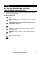
Safety IMPORTANT SAFETY INSTRUCTIONS - SAVE THESE INSTRUCTIONS This manual contains important instructions that must be followed during installation, operation, and maintenance of the InfraStruXure System. Symbols used in this manual Electrical Hazard: Indicates an electrical hazard which, if not avoided, could result in injury or death. Danger: Indicates a hazard which, if not avoided, could result in severe personal injury or death.
Warnings Installation/Maintenance Only a certified electrician can perform these tasks: • Connect the Power Distribution Unit (PDU) to utility power • Install an upstream circuit breaker • Route and connect the power cables for under-floor wiring • Connect a switch to the Emergency Power Off (EPO) interface on the PDU Only a certified electrician or an APC Field Service Engineer can perform these tasks: • Connect the PDU to the Symmetra PX UPS • Perform maintenance of the PDU bo Install a circuit breaker t
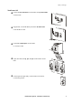
Safety: Warnings Total Power Off Set the UPS DC Disconnect circuit breaker and System Enable px0003a switch to OFF. If applicable, set the XR Battery Enclosure DC Disconnect circuit breaker to OFF. Set the PDU Main Input circuit breaker (or switch) to OFF. Open (turn OFF) the Q1, Q2, and Q3 circuit breakers on the PDU. Set the upstream input utility circuit breaker to the OFF or gen0137a Locked Out position.
Safety: Warnings DANGER—Risk of Electric Shock! Electrical Hazard: Hazardous, live parts inside the Symmetra PX UPS are energized from the battery supply even when the AC power is disconnected. Hazardous, live parts may exist inside the InfraStruXure PDU because of the Symmetra PX UPS inverter even when the AC power is disconnected. Test any electrical parts before touching them.
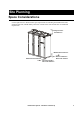
Site Planning Space Considerations Use the figure below to determine the space requirements for installing the InfraStruXure PDU, Symmetra PX UPS, and XR Battery Enclosure. Consult local codes and the NEC for additional requirements.
Installation Procedures Installation Procedure Overview This section provides the basic steps to install the InfraStruXure power and rack components. Follow the references provided with each step for detailed instructions. Warning: Do not begin installing your InfraStruXure system without an APC Field Service Engineer present. Note: Search all boxes and packaging to make sure that they are empty before discarding. 1.
Installation Procedures: Installation Procedure Overview 6. Connect utility conductors to the PDU. For instructions, see “Connect Utility Conductors to the PDU” on page 14. 7. Connect AC power and control wiring. See “Connect AC Power and Control Wiring” on page 18 for detailed instructions. 8. Connect DC power wiring, if applicable. See “Connect DC Power Wiring, if Applicable” on page 20 for detailed instructions. 9 .
Installation Procedures: Installation Procedure Overview 16. Configure the InfraStruXure Manager. For instructions, see the manual included with your InfraStruXure Manager. Tools Required The following tools are required to perform the procedures in this manual. Additional tools may be required for components not covered in this manual.
Level the PDU, UPS, NetShelter, and XR Battery Enclosures Leveling feet are attached under the enclosure at each corner. The leveling feet can help provide a stable base if the selected floor space is uneven, but they are not intended to compensate for a badly sloped surface. To level the enclosure: 1. Use a 14-mm end of the open-ended wrench (provided) to extend the leveling foot until it makes firm contact with the floor. 2. Repeat step 1 for each of the remaining leveling feet. 3.
Exchange Side Panels Before installing the InfraStruXure PDU, Symmetra PX UPS, and XR Battery Enclosure, exchange side panels so that the adjacent panels will have matching holes for joining the enclosures together and for routing input and output wiring between them.
Installation Procedures: Exchange Side Panels psx0020a 3. Remove the side panels from the sides of the PDU and XR Battery Enclosure that will not be adjacent to the UPS. 4. Remove the rear hole covers from the panels that you removed in step 3. Connect Battery Enclosure communication cables 2. Connect the cable to Port 1 on the first adjacent XR Battery Enclosure’s XR Communication Card. Com m.
Join the PDU, UPS, and XR Battery Enclosures 1. Move the PDU, Symmetra PX UPS, and XR Battery Enclosures into position, aligning the holes in the adjacent side panels. 2. Level the PDU, Symmetra PX UPS, and XR Battery Enclosure by using a level and adjusting the leveling feet on each enclosure. 3.
Connect Utility Conductors to the PDU Electrical Hazard: A licensed electrician must connect input conductors to the PDU! Access the PDU Main Input switch 1. Open the back doors of the PDU, unlock the top, smaller door, using the provided red key. 2. Loosen the two screws holding the larger, hinged door in place. Attach conduit to the PDU for the input conductors 1.
Installation Procedures: Connect Utility Conductors to the PDU For overhead wiring: Remove the user connection plate from the top of the PDU. 2. Cut an appropriately-sized hole in the gland plate for the conduit. 3. Re-attach the gland plate. 4. Install a lock-nut and bushing to the conduit. 5. Thread the conduit through the hole. Install a circuit breaker Warning: When you connect the InfraStruXure PDU to utility, you must install a circuit breaker to protect the PDU against over-current.
Installation Procedures: Connect Utility Conductors to the PDU Route the input conductors to the Main Input switch For overhead wiring, run the input conductors directly to the Main Input switch. For wiring under a raised floor, run the input conductors through the wireway () within the PDU to the Main Input switch. Connect input conductors Electrical Hazard: A licensed electrician must connect input conductors to the PDU! Torque specs and tools required.
Installation Procedures: Connect Utility Conductors to the PDU At the Main Input switch, connect the input wiring according to the labels on the switch and the illustrations below. Warning: Connect the conductors to the terminals according to the labels on the terminals. Use copper conductors only.
Connect AC Power and Control Wiring Electrical Hazard: Only Field Service Engineers or qualified personnel trained by APC may connect the AC power and control wiring. Connect AC power and control wiring to the UPS. There are five input wires and four output wires coiled on the floor of the PDU. Each set of wires is labeled. The control wires for the UPS Maintenance Bypass control board and the UPS EPO control board are also coiled in the PDU.
Installation Procedures: Connect AC Power and Control Wiring Connect control wiring. 1. Connect the EPO control wires from the PDU and the XR Battery Enclosure (if applicable) to the EPO board on the UPS. The control wires are harnessed and coiled in the floor of the PDU and the XR Battery Enclosure. The PDU harness connects to J6 and the XR Battery Enclosure harness connects to J8. 2. Connect the Maintenance Bypass control wire harness from the PDU to the Maintenance Bypass interface board of the UPS.
Connect DC Power Wiring, if Applicable Electrical Hazard: Only Field Service Engineers or qualified personnel trained by APC may connect the XR Battery Enclosure to the Symmetra PX UPS or to another XR Battery Enclosure. Warning: The supplied power and ground wires are for internal side-panel wiring only. These wires are not for use in external conduits. Electrical Hazard: Before you begin connecting the DC power wiring, ensure that there are no battery units installed in the XR Battery Enclosures.
Installation Procedures: Connect DC Power Wiring, if Applicable Connect power cables from the XR Battery Enclosure to the Symmetra PX UPS 1. Route the XR Battery Enclosure DC output cables to the Symmetra PX UPS through the hole in the adjacent side panels. 2. Connect the XR Battery Enclosure DC output cables to the Symmetra PX UPS DC input terminal [(+) to (+), (CT) to (CT), (–) to (–)].
Connect an Emergency Power Off Switch Overview To provide a mechanism for emergency power off, attach a remote switch (not included) to the EPO interface on the PDU monitoring unit. The EPO interface () is connected to the PDU Main Input switch () and to the UPS internal EPO switch (). When the EPO is activated, the main input breaker to the PDU transformer is opened, the UPS DC Disconnect breaker is opened, and the UPS System Enable switch is turned off.
Installation Procedures: Connect an Emergency Power Off Switch Connect an EPO switch to the user connection plate 1. Connect the switch to the EPO connection point terminals located on the bottom side of the PDU user connection plate.
Connect User Input Contacts and Relay Outputs to the User Connection Plate Overview Make contact closure connections (NO or NC) at the user connection plate to monitor dry contacts. You can make up to four input contacts and four relay output connections. The figure at the right shows the location of the user connection plate on the roof of the PDU enclosure. Make the connections from inside the enclosure, or remove the user connection plate and make the connections.
Route and Attach Power Cables to the Racks Overhead Wiring Route and attach power cables to equipment racks. If you ordered overhead wiring, connect the prewired power cables of the InfraStruXure PDU as follows: 1. Install the Shielding Troughs, Shielding Partitions, and Cable Ladders so that you can route power cables from the PDU to the Netshelter Enclosures. 2. Find the numbers that indicate the enclosure to which each power cable will supply power.
Installation Procedures: Route and Attach Power Cables to the Racks – For single-feed devices within a redundant system with an Automatic Transfer Switch: connect a power cable to the Automatic Transfer Switch (A and B feeds) and connect the Automatic Transfer Switch power cord to a Rack PDU in the NetShelter VX Enclosure.
Installation Procedures: Route and Attach Power Cables to the Racks application) from the enclosure through the Liquidtite conduit to the PDU. 4. At the PDU, route the cable through the opening you created in step 1 and then up through the wireway () at either side of the PDU. This will allow you to connect the cable to the circuit breaker panel. 5. At the circuit breaker panel, cut the wires to the proper length, and connect the power cable’s individual wires: a.
Route Data Cables to the InfraStruXure Manager Hub (or Switch) 1. Connect a CAT-5 network cable (provided) to the network or 10BaseT ports on your APC InfraStruXure devices. The following devices need to be connected: Automatic Transfer Switch Environmental Monitoring Unit Rack PDU Symmetra PX UPS InfraStruXure PDU 2. Run the connected CAT-5 network cables through the data cable troughs to the InfraStruXure Manager Hub (or Switch). 3.
Start-Up Procedure Apply power to the system Safety warnings This section provides instructions on how to perform a system start-up. Do not skip any steps in this procedure. Electrical Hazard: Only APC Field Service Engineers or qualified, APC-trained personnel may perform a system start-up. Ensure that all power is off. See “Total Power Off” on page 3. Warning: Do not install any batteries into the XR Battery Enclosure or power modules into the Symmetra PX UPS until instructed to do so. 1.
6. Install at least one battery module (four battery units) in the Symmetra PX UPS. Install battery modules, starting in the lowest available shelf. Position the battery unit between the grooves, and slide it completely into the enclosure. Heavy: Use two people to lift and install battery units. Electrical Hazard: The DC bus in the Symmetra PX UPS is energized when battery modules are installed, even when the DC Disconnect circuit breaker is open. px0012a 7.
Start-Up Procedure: Apply power to the system px0019a 8. Secure the power module: a. Tighten the screws on each side of the power module. b. Turn the locking latch clockwise until the arrow on the knob faces the power module. Note: The power module will not start unless the locking latch is engaged. px0013a 9. Set the UPS DC Disconnect circuit breaker to ON, and then set the UPS System Enable switch to ON. 10. If applicable, set the XR Battery Enclosure DC Disconnect circuit breaker to ON.
Start-Up Procedure: Apply power to the system Verify UPS battery operation 1. Read the messages displayed on the Symmetra PX UPS display interface. Note any alarms and verify that they are appropriate for start-up conditions. Top-Level Status Screen 2. Command the UPS to apply power to the load: a. Press the ESC key to open the top-level menu. b. Select Control, and press the ENTER key. c. Select Turn Load On from the Control menu, and press the ENTER key.
Start-Up Procedure: Apply power to the system 3. Command the UPS to turn off power to the load: a. Press the ESC key at the top-level status screen to open the top-level menu and have access to eight submenus. b. Select Control, and press the ENTER key. c. Select Turn Load Off from the Control menu, and press the ENTER key.
Start-Up Procedure: Apply power to the system Verify proper voltage and phase rotation at the UPS 1. Close (turn ON) the Q1 circuit breaker on the PDU to apply power to the UPS. 2. Ensure A-B-C clockwise rotation at the UPS input terminal block, using a phase rotation meter. 3. Verify proper voltage is present at the UPS input terminal block (208V, metered phase-to-phase), using a true RMS voltmeter. Start the UPS px0013a 1.
Start-Up Procedure: Apply power to the system 3. Read the messages displayed on the Symmetra PX UPS display interface. Note any alarms and verify that they are appropriate for start-up conditions. Top-Level Status Screen 4. Command the UPS to apply power to the load: a. Press the ESC key to open the top-level menu. b. Select Control, and press the ENTER key. c. Select Turn Load On from the Control menu, and press the ENTER key.
Start-Up Procedure: Apply power to the system Verify bypass operation 1. Command the UPS into static bypass operation through the UPS display interface: a. Press the ESC key to open the top-level menu. b. Select Control on the top-level menu, and press the ENTER key. c. Select UPS Into Bypass on the Control menu, and press the ENTER key.
Start-Up Procedure: Apply power to the system 3. Close (turn ON) the Q3 circuit breaker on the InfraStruXure PDU. Note: The H2 LED above the Q2 circuit breaker illuminates, indicating that it is safe to operate the Q2 circuit breaker. 4. Open (turn OFF) the Q2 circuit breaker on the InfraStruXure PDU. The UPS will display a Forced Bypass message on the display interface and the Fault LED will be red. 5. Command the UPS into static bypass operation through the UPS display interface: a.
Start-Up Procedure: Apply power to the system 6. Close (turn ON) the Q2 circuit breaker on the InfraStruXure PDU. Note: The H3 LED above the Q3 circuit breaker illuminates, indicating that it is safe to operate the Q3 circuit breaker. 7. Open (turn OFF) the Q3 circuit breaker on the InfraStruXure PDU. 8. Command the UPS out of static bypass operation through the UPS display interface: a. Press the ESC key at the top-level status screen to open the top-level menu and have access to eight submenus. b.
Start-Up Procedure: Apply power to the system 2. Close (turn ON) the PDU distribution panel breakers. Note: When the distribution panel circuit breakers are closed, the PDU power cables and connected equipment are energized. Configure the InfraStruXure Manager Once all equipment is installed, the network cables are connected to the InfraStruXure Manager hub (or switch), and start-up of the system is complete, configure the InfraStruXure Manager.
Specifications 40 kW InfraStruXure PDU Electrical PD40F6FK1-M PD40G6FK1-M PD40L6FK1-M Nominal Voltage Requirements 208/120 V 480/277 V 600/346 V Nominal Current 125 A 54 A 43 A Frequency 57–63 Hz 57–63 Hz 57–63 Hz 175 AT 80 AT 60 AT 3/0 AWG #3 AWG #4 AWG UPS Breaker Size 175 AT 175 AT 175 AT Maximum Continuous Current 155 A 67 A 54 A Grounding PE node (from AC or floor grid) Input Voltage Configuration Transformer 3W + G + GEC Without Transformer Upstream Circuit Breaker M
Specifications: 40 kW InfraStruXure PDU Electrical PD40F6FK1-M Power Cable Lengths Recommended Wire PD40G6FK1-M PD40L6FK1-M various Sizing‡ L1, L2, L3, N 3/0 AWG 4 AWG 4AWG G 6 AWG 8 AWG 8 AWG GEC 4 AWG 4 AWG 4 AWG Power Cable—top Accommodates 28, 3-phase power cables (42 knockouts) Power Cable—bottom Accommodates 28, 3-phase power cables (48 knockouts) Panel Boards Panel Style 3-phase Number of Panels per PDU 2 maximum Positions per Panel 42 3-Phase Breakers per Panel 14 maxi
Specifications: 40 kW InfraStruXure PDU Physical PD40F6FK1-M PD40G6FK1-M PD40L6FK1-M 72A 58A Configuration Delta to WYE Maximum Power Rating 60kVA Maximum Current Rating 166A Construction Cu windings, open core Temperature Rating 220° C (Class H) Maximum Temperature Rise 150°C Efficiency 97–98% Environmental Operating Environment Protected from water and conductive contaminates Temperature Operating 32 to 104° F (0 to 40° C) Storage 32 to 113° F (0 to 45° C) Class Class H (220° C
APC Worldwide Customer Support Customer support for this or any other APC product is available at no charge in any of the following ways: • Visit the APC Web site to access documents in the APC Knowledge Base and to submit customer support requests. – www.apc.com (Corporate Headquarters) Connect to localized APC Web sites for specific countries, each of which provides customer support information. – www.apc.com/support/ Global support searching APC Knowledge Base and using e-support.