
Installation guide


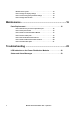
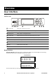
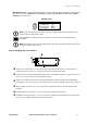
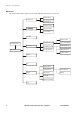
Table Of Contents
- About this Manual
- Companion manuals
- How to find updates to this manual
- Safety
- IMPORTANT SAFETY INSTRUCTIONS - SAVE THESE INSTRUCTIONS
- Symbols used in this manual
- Regulatory Agency Approval
- Overview
- User Interface
- Interface area
- Display Interface
- How to navigate the user interface
- Menu tree
- Operation
- Operation Procedures
- How to perform a total power off procedure
- How to view the Power Distribution Module status
- How to view Power Distribution Module information
- How to view circuit status information
- How to view output voltages
- How to view the log
- How to clear the log
- How to view the list of active alarms
- Configuration
- Settings
- How to set up the network
- How to set the name and location of the circuits
- How to set the individual alarm thresholds
- How to set the alarm thresholds for all Power Distribution Modules in the system
- How to change the display settings
- How to set and change the password settings
- How to change date and time
- Maintenance
- Parts Replacement
- How to determine if you need a replacement part
- How to return parts to APC
- How to install a Power Distribution Module
- How to remove a filler plate
- How to test the Residual Current Device
- How to install a PDM circuit breaker handle tie
- How to reinstall a filler plate
- Troubleshooting
- LED Indication on the Power Distribution Modules
- Status and Alarm Messages
2 Modular Power Distribution Unit – Operation 990-3054B-001
Overview
User Interface
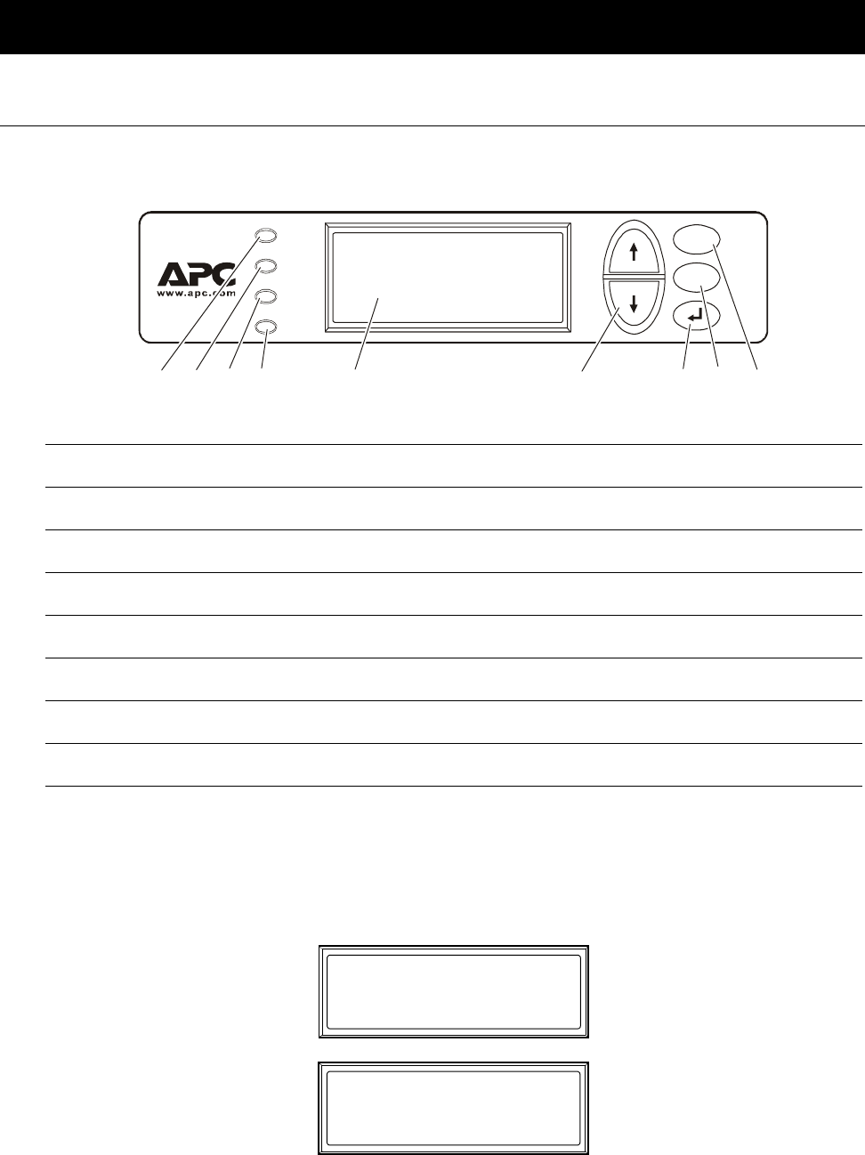
Interface area
Display Interface
Overview Screens. When the system is running, the display will scroll through screens showing
information on the status of the PDU and any active alarms.
The
ENTER key takes you from the Overview Screens to the Main Menu Screen.
Normal LED When green, no alarms are present.
Check Log LED When green, a new event has been added to the log.
Warning LED When yellow, a warning alarm exists.
CriticaL LED When red, there are one or more critical alarms in the system.
LCD SCREEN Displays alarms, status data, instructional help, and configuration items.
UP and DOWN keys Scrolls through menu items.
ENTER Opens menu items and confirms changes to system parameters.
HELP Opens context-sensitive help.
ESC Returns to previous screen.
ESC
?
Normal
Check
Log
Warning
Critical
No Active Alarms
System Date/Time:
28-May-2007 10:37:01
Overview Screens
Output Voltage
L1: xxx L1-2: xxx
L2: xxx L2-3: xxx
L3: xxx L3-1: xxx