Operation Smart-UPS® VT ISX 20-30 kVA 208/480 V
Contents Introduction.............................................................1 UPS Overview ..........................................................2 User Interface . . . . . . . . . . . . . . . . . . . . . . . . . . . . . . . . . . . . . . 3 APC Network Management Card AP9619 (installed in UPS) with Temperature Sensor . . . . . . . . . . . . . . . . . . . . . . . . . . . . . . 4 The Display . . . . . . . . . . . . . . . . . . . . . . . . . . . . . . . . . . . . . . . . 5 Navigation . . . . . . . .
– Maintenance ......................................................... 22 Battery Replacement . . . . . . . . . . . . . . . . . . . . . . . . . . . . . . . . 22 Battery Modules . . . . . . . . . . . . . . . . . . . . . . . . . . . . . . . 22 Battery Module removal . . . . . . . . . . . . . . . . . . . . . . . . . . 22 Battery Module Installation . . . . . . . . . . . . . . . . . . . . . . . . 23 Network Management Card Replacement . . . . . . . . . . . . . . . . 25 How to Obtain Orderable Parts . . . . .
Introduction Welcome to the Operation manual covering the Smart-UPS® VT ISX. This manual provides you with a detailed description of operation, maintenance, troubleshooting and restart. Separate manuals are available on: • Safety – part no. 990-2822 Read the Safety sheet for information on Total Power Off and general information on safety. Read the Safety sheet prior to handling/using the UPS system. Note • Receiving and Unpacking – part no. 990-2821 • Installation – part no. 990-2812.
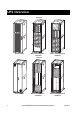
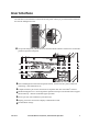
UPS Overview Front view ! Output Pwr Zone Probe 10/100Base-T Reset 10/100 AP9619 Network Management Card EM ! Output Pwr Zone Probe 10/100Base-T Reset 10/100 AP9619 Network Management Card EM Serial: Model: BATTERY UNIT Serial: Model: BATTERY UNIT Serial: Model: BATTERY UNIT Serial: Model: BATTERY UNIT Serial: Model: BATTERY UNIT Serial: Model: BATTERY UNIT Serial: Model: BATTERY UNIT Serial: Model: BATTERY UNIT Serial: Model: BATTERY UNIT Serial: Model: BATTERY UNIT Ser
User Interface The UPS has a lock mechanism on the front and rear panels. The key is provided with the manual for the Network Management Card. To open the front panel, pull out the lower end of the handle and turn it clockwise to a horizontal position to open the front panel.
UPS Overview – User Interface APC Network Management Card AP9619 (installed in UPS) with Temperature Sensor Temperature Sensor ! Output Pwr Zone Probe 10/100Base-T Reset 10/100 AP9619 Network Management Card EM The APC Network Management Card with temperature sensor is installed in the UPS. It is used for remote system control and monitoring, e-mail notifications etc.
The Display The four LEDs to the left of the display indicate the operational status of the UPS. The five navigation keys to the right are used to select and open menu items, to access information, change system parameters, and to launch context-sensitive help. LOAD ON ON BATT BYPASS ESC Chrg 100% Load 000% 120Vin 000Vout 60Hz Runtime: 00hr 30m ? FAULT LOAD ON When the green LED is on, the UPS provides power to the load equipment.
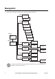
Navigation The menu tree provides a quick overview of the user interface functions. The menu tree provides a quick overview of the user interface functions.
UPS Overview – Navigation Basic display navigation principles All illustrated display screens are examples only! Note On the display, press ESC until you get to the Overview Screen, which provides you with basic system status information. Press UP, DOWN arrows to navigate the selector arrow and view all sub-menu screens. Chrg 100% Load 000% 120Vin 000Vout 60Hz Runtime: 0hr 0m Overview Screen Press ENTER to open the Main Menu screen. From here, you command, configure, and monitor the system.
UPS Overview – Navigation Switch load OFF (disconnect the UPS output to the load equipment): • From the Main Menu, select Control and press ENTER • Use UP/DOWN key to navigate to Turn Load Off, and press ENTER • Select YES, Turn Load Off Switch load ON: • From the Main Menu, select Control and press ENTER • Use UP/DOWN key to navigate to Turn Load On, and press ENTER • Select YES, Turn Load On Switch into bypass: • From the Main Menu, select Control and press ENTER • Use UP/DOWN key to navigate to UPS i
UPS Overview – Navigation Frequencies. Utility frequency, bypass frequency and output frequency in Hertz (Hz). Load and batteries. Load: Percentage of the load in relation to the total UPS capacity. Bat Voltage: shows either the positive or negative half of the battery voltage (the lower value of the two will appear). Bat Cap: Percentage charge on the batteries in relation to the total battery capacity. Runtime: The predicted runtime at the current load. Batteries.
UPS Overview – Navigation Time • To change the time, press ENTER (the hour field will become active). Press the UP/DOWN arrow to select the desired time. • Follow the same procedure to change the minute and the second fields. • Press ENTER to save, or ESC to cancel. Press ESC to return to the Main Menu. Logging From the logging screen on the Main Menu, you can view the 100 most recent UPS log events, and view the logged details of the events, such as date and time of occurrence, and event number.
UPS Overview – Navigation View Statistics (submenu under Logging). From the Logging screen on the Main Menu, you can view the statistics on operation mode changes, inverter time, duration of battery operation. Control Status Setup Logging Display Diags Help Main Menu • From the Main Menu, select Logging • Select View Statistics • Press ESC to return to Main Menu Alarm threshold If the load level exceeds the preprogrammed threshold, the UPS will display a warning. Example: Alarm Thresholds Load: 20.
UPS Overview – Navigation To change the language, select Language, and press ENTER. The Language line is now active. Use the UP/DOWN arrows to select the desired language. Press ENTER to confirm your selection. Contrast setting. From the Display Setup Menu, select Contrast. To change the contrast, select Contrast, and press ENTER. Use the UP/DOWN arrows to select the contrast level - the lower the number, the darker the contrast. Select ENTER to confirm the setting. Beeper setup.
UPS Overview – Navigation Control Status Setup Logging Display Diags Help Main Menu • From the Main Menu, select Diags, and press ENTER • Use UP/DOWN arrow to select Fault and Diagnostics and press ENTER For more details on Fault and Diagnostics screens, see the Troubleshooting section.
Operation Modes In a stand-alone installation, the UPS has four different operating modes. Normal operation During normal operation, the UPS converts utility power to conditioned power for the connected load. Battery operation During battery operation, the UPS provides power to the connected load from its internal and (if applicable) external batteries for a finite period. The UPS transfers to battery operation if the supply of utility power fails, or is outside pre-defined limits.
UPS Overview – Operation Modes Turn into mechanical bypass using the Mechanical Bypass Lever The load is not protected by the UPS when the internal mechanical bypass system is active, and, the power is not conditioned. Caution If the UPS is running and controllable through the display, carry out steps 1 through 6. If not, go directly to step 4. Note Control Status Setup Logging Display Diags Help Main Menu From the Main Menu, select Control and press ENTER.
UPS Overview – Operation Modes Turn into normal operation (from mechanical bypass operation) Caution Never attempt to switch back the UPS into normal operation till you have verified that there are no internal UPS faults. Call APC Customer Support (see rear cover of this manual) before returning to normal operation. Verify the presence of utility supply. UPS will start up and perform self test (see Restart Procedure).
Restart Procedure Start-up is included with the UPS, and the start-up procedure described here is only applicable if the UPS requires a subsequent start-up. Note Power application Only trained personnel familiar with the construction and the equipment may carry out the restart procedure. Warning Set the utility breaker to the ON position. If your installation includes a Battery Enclosure with a DC disconnect switch, set the DC disconnect switch to the ON position.
UPS Overview – Restart Procedure Voltage confirmation See display introduction under The Display. At the restart, the display will prompt you through the following screens: Confirm Voltage Use 208V Yes, use 208V No, select another • When the Confirm Voltage prompt appears on the screen, select desired voltage and press ENTER. Apply load? Yes No • When the prompt Apply load appears, select Yes if you want the UPS to provide a load output now.
Load Connection At the rear, the UPS contains at least one Distribution Units (PDU). As standard, one PDU is installed on the left side seen from the rear. In addition, a second PDU may be installed on the right side. The PDU has 6 breaker sets. The top breaker set operates as a unit and protects any 3-phased equipment that may be connected to the PDU. This breaker unit (must be toggled) will switch ON/OFF all 3 phases when operated (may supply several loads).
Load Connection – Restart Procedure Set the applicable breaker to the OFF position (make a note of which outlet supplies which load). Insert the plug from the load into the outlet. Secure the plug by turning it clockwise approximately 45°. Set the applicable breaker to the ON position to supply the load. Note The UPS can support a 3-phase load if that load is connected to the 3-phase terminal in order to ensure correct connection/disconnection of the load across all 3 phases simultaneously.
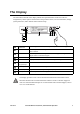
Load Connection – Restart Procedure PDU output breaker ratings Nominal rating of breaker Rear of unit Ambient temperature in front of unit ºC 20 50 63 Free exhaust 20 17 42.5 53.55 Free exhaust 30 16 40.0 50.40 Free exhaust 40 15 37.5 47.25 Hot aisle exhaust 25 16 40.0 50.
Maintenance Battery Replacement Read the Safety sheet prior to replacing parts (available in the Documentation Storage Area). Note Battery Modules One Battery Module consists of 4 Battery Units. Serial: Model: BATTE RY UNIT Serial: Model: BATTE RY UNIT Serial: Model: BATTE RY UNIT Serial: Model: BATTE RY UNIT 4 x 50 lb / 4 x 24 kg Battery Module removal Use two people to lift components weighing between 40 – 70 lb / 18 – 32 kg.
Maintenance – Battery Replacement ! Output Pwr Zone Probe 10/100Base-T Reset 10/100 AP9619 Network Management Card EM Serial: Model: BATTERY UNIT Serial: Model: BATTERY UNIT Serial: Model: Serial: Model: BATTERY UNIT BATTERY UNIT Serial: Model: BATTERY UNIT Serial: Model: BATTERY UNIT Serial: Model: BATTERY UNIT Serial: Model: BATTERY UNIT Serial: Model: BATTERY UNIT Serial: Model: BATTERY UNIT Serial: Model: BATTERY UNIT Serial: Model: BATTERY UNIT Serial: Model: BA
Maintenance – Battery Replacement Serial: Model: BATTERY UNIT Serial: Model: BATTERY UNIT Install batteries in the lowest available bay. Position the battery to slide in between the grooves and push completely into the UPS to ensure connection. If a problem is reported, ensure that the modules in question are correctly installed. If the problem persists, refer to the Troubleshooting section.
Network Management Card Replacement ! Output Pwr Zone Probe 10/100Base-T Reset 10/100 AP9619 Network Management Card EM ! Output Pwr Zone Probe 10/100Base-T Reset 10/100 AP9619 Network Management Card EM Serial: Model: BATTERY UNIT Serial: Model: BATTERY UNIT Serial: Model: BATTERY UNIT Serial: Model: BATTERY UNIT Serial: Model: BATTERY UNIT Serial: Model: BATTERY UNIT Serial: Model: BATTERY UNIT Serial: Model: BATTERY UNIT Serial: Model: BATTERY UNIT Serial: Model: B
How to Obtain Orderable Parts To obtain a orderable part, contact APC Customer Support (see rear cover). • In the event of a Battery Module failure, the display may show additional “fault list” screens. Press any key to scroll through these fault lists, record the information, and report it to APC. • If possible, call APC Customer Support from a telephone that is within reach of the UPS display interface so that you can gather and report additional information to the APC.
Troubleshooting This section lists the status and alarm messages that the UPS might display. The messages are listed in alphabetical order, and a suggested corrective action is listed with each alarm message to help you troubleshoot problems. Display messages Display message Meaning Corrective action Automatic Self Test Started. The UPS has started pre-programmed battery test. No corrective action necessary. Batt Temperature Exceeded Upper Limit.
Troubleshooting – How to Obtain Orderable Parts 28 Display message Meaning Corrective action Load Is No Longer Above Alarm Threshold. The load previously exceeded the alarm threshold and the situation has been corrected either because the load decreased or the threshold was increased. No corrective action necessary. Load Power Is Above Alarm Limit. The load has exceeded the userspecified load alarm threshold. Option 1: Use the display interface to raise the alarm threshold.
Troubleshooting – How to Obtain Orderable Parts Display message Meaning Corrective action System Failure Detected by Surveillance. The system has detected an internal error. Check for other alarms and contact APC customer support if problem persists. System Start Up Configuration Failed. System configuration error. Unable to determine system voltage and/or Enclosure size. Check for other alarms and contact APC customer support if problem persists. System Not Synchronized to Bypass.
APC Worldwide Customer Support Customer support for this or any other APC product is available at no charge in any of the following ways: • Visit the APC Web site to access documents in the APC Knowledge Base and to submit customer support requests. – www.apc.com (Corporate Headquarters) Connect to localized APC Web sites for specific countries, each of which provides customer support information. – www.apc.com/support/ Global support searching APC Knowledge Base and using e-support.