Unpacking, Installation, and Customization NetShelter® SX Enclosure U.S. Patent No.
This manual is available in English on the enclosed CD. Dieses Handbuch ist in Deutsch auf der beiliegenden CD-ROM verfügbar. Este manual está disponible en español en el CD-ROM adjunto. Ce manuel est disponible en français sur le CD-ROM ci-inclus. Questo manuale è disponibile in italiano nel CD-ROM allegato. 本マニュアルの日本語版は同梱の CD-ROM からご覧になれます。 Instrukcja Obsługi w jezyku polskim jest dostepna na CD. O manual em Português está disponível no CD-ROM em anexo.
Contents Product Overview ........................................................... 1 Description . . . . . . . . . . . . . . . . . . . . . . . . . . . . . . . . . . . . . . . . . . . . . 1 NetShelter SX Enclosures . . . . . . . . . . . . . . . . . . . . . . . . . . . . . . . . . 1 Product Inventory . . . . . . . . . . . . . . . . . . . . . . . . . . . . . . . . . . . . . . . . 2 Components of the enclosure . . . . . . . . . . . . . . . . . . . . . . . . . . . . . . 2 Before Installation ...............
Removing and Installing the Doors . . . . . . . . . . . . . . . . . . . . . . . . . 13 Removing the doors . . . . . . . . . . . . . . . . . . . . . . . . . . . . . . . . . . . . . 13 Installing the doors . . . . . . . . . . . . . . . . . . . . . . . . . . . . . . . . . . . . . . 14 Reversing the front door . . . . . . . . . . . . . . . . . . . . . . . . . . . . . . . . . . 15 Vertical Mounting Flanges . . . . . . . . . . . . . . . . . . . . . . . . . . . . . . . .
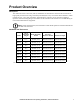
Product Overview Description The American Power Conversion (APC®) NetShelter® SX 600-mm and 750-mm wide enclosures are high-quality enclosures for storage of industry-standard (EIA-310), 19-inch rack-mount hardware, which includes servers, voice, data, networking, internetworking, and APC power protection equipment. Optional vertical mounting flanges are available for the 750-mm wide enclosure for accommodating 23in EIA telecommunications equipment.
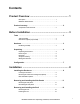
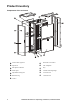
Product Inventory Components of the enclosure Vertical cable organizer Reversible curved door Split doors APC nameplate Side panels with locks Key Frame posts Vertical mounting flanges Adjustable leveling feet 1070-mm roof Hardware bag 1200-mm roof Casters 2 NetShelter SX Enclosure: Unpacking, Installation, and Customization
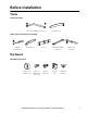
Before Installation Tools Tools (provided) Torx® T30/#2 Phillips wrench (1) Cage nut tool (1) Other tools required (not provided) Phillips screwdriver (1) Utility knife (1) Level (1) 13-mm open-ended wrench (1) 10-mm socket wrench (1) Hardware Hardware (provided) Plastic cup washers (60) M6 x 16 Phillips slot screws (60) M5 x 12 screws (4) Cage nuts (60) 7-mm hole plugs (4) NetShelter SX Enclosure: Unpacking, Installation, and Customization 3
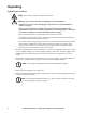
Unpacking Unpacking the enclosure Heavy: Use at least two people to unpack the enclosure. Warning: To prevent the enclosure from tipping over after installation: • Stabilize the enclosure before installing the components. See “Rack stabilization options” on page 9. • Do not extend components on sliding rails out from the enclosure until you have installed three or more pieces of similar equipment, or the stabilizer plate or bolt-down brackets are installed. See “Rack stabilization options” on page 9.
5. With one person on each side of the enclosure, carefully roll it toward the rear of the pallet until the rear casters clear the back edge of the pallet. Continue to slide the enclosure rearward until the rear casters touch the floor. 6. While one person carefully tips the enclosure slightly away from the pallet, have the other person pull the pallet away from the enclosure. Set the enclosure gently on its casters. Note: Save the pallet if you plan to reship the enclosure. 7.
Moving the enclosure Casters. The enclosure can be moved on its casters with up to 1021 kg (2,250 lbs) of equipment installed. Push the enclosure from the front or the back, not the sides; it may be unstable when pushed from the side. For greater stability, load 159 kg (350 lbs) or more of equipment into the enclosure before moving it on its casters. Eye bolts. If lifting of the enclosure is necessary, this can be done by attaching eye bolts (not included) to the top of the enclosure frame.
Configuration Before installing the enclosure, plan the location and space needed to install equipment, and plan the ergonomics of keyboards and video monitors. The Rack Configurator, available on the APC Web site, www.apc.com, helps you plan your configuration to maximize the available U-space of your enclosures. Caution: Improper airflow could damage installed components. To maintain proper airflow, cover any empty vertical enclosure space with blanking panels (not included).
Installation Installing the Enclosure Warning: For extra stability, load 158 kg (350 lbs) of equipment into the bottom of the enclosure before moving it on its casters. Leveling the enclosure Level the enclosure before installing equipment. The leveling feet at the corners provide a stable base if the floor is uneven, but they cannot compensate for a badly sloped surface. You can remove the casters and leveling feet to allow the base of the enclosure to rest directly on the floor. 1.
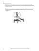
Removing the casters and leveling feet (optional) Warning: To avoid personal injury or damage to the enclosure, two people should support the enclosure. The enclosure should be empty and the roof, side panels, and front and rear doors should be removed before laying the enclosure on its side. Tilt the enclosure in an area that will allow for proper clearance above the enclosure. 1. Lay the enclosure on its side. 2.
APC offers the following brackets for providing stabilization. Product Stabilizer Plate Kit Bolt-down Kit Pallet Mounting Bracket (provided) 10 SKU Description AR7700 Attaches externally to the rack and floor to provide additional stability. AR7701 Attaches to rack and floor internally or externally to provide additional stability without blocking cable access. Figure Attaches to rack and floor internally or externally to provide additional stability.
Removing and Installing the Side Panels Remove the side panels to access the interior or pass cables between the enclosures when joining enclosures together. Side panels offer additional security and assist with proper airflow within the enclosure. Removing the side panels 1. Use the key to unlock the panel, if necessary. 2. Slide the panel latch down and pull the top of the panel away from the enclosure. 3.
Removing and Installing the Roof Removing the roof 1. Pull and hold the two spring pins in the rear of the enclosure. 2. Push the roof up from the enclosure. 3. Lift the roof off the enclosure. Installing the roof 1. Slide the tabs on the front of the roof into the slots in the front of the enclosure. 2. Lower the roof into the enclosure, while pulling the two spring pins in the rear of the roof. 3. Release the pins to secure the roof to the enclosure.
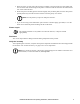
Removing and Installing the Doors Note: If the enclosures are joined together, see “Removing the Doors of Joined Enclosures” on page 32. Warning: To avoid personal injury or damage to the enclosure, one person should support the door while another person removes the door from its frame. Removing the doors You can remove the front and rear doors of the enclosure to gain better access to equipment. 1. Disconnect the grounding wire. ns0928a 2.
Reversing the front door 1. Remove the APC nameplate from the front door. 2. Remove the M6 x 12 pan-head screws and star washers that secure the grounding wire to the frame and door, using the Torx T30/#2 Phillips wrench (provided). 3. Remove the two Phillips screws from the rear of the door handle assembly, and remove the handle assembly from the door.
4. Remove the screw, latch, and washer from the back of the door handle assembly using the Torx T30/#2 Phillips wrench (provided). Rotate the washer 90 degrees and the latch 180 degrees and reattach the latch. 5. Remove the door. See “Removing the doors” on page 13. 6. Remove the hinges from the frame using the Torx T30 /#2 Phillips wrench (provided). Rotate the hinges 180 degrees, and reinstall them on the other side of the frame of the enclosure.
7. Remove the hinges from the door and reinstall them using the set of holes directly below where they were originally installed. 8. Rotate the door 180 degrees and reinstall the door. See “Installing the doors” on page 13. 9. Reinstall the grounding wire at the top of the door, near the hinges, and to the enclosure frame using the M6 x 12 pan-head screw and star washer. 10. Rotate the door handle assembly 180 degrees and reinstall it using the screws removed in step 2. 11.
Vertical Mounting Flanges Vertical mounting flanges come factory-installed on the enclosure in the proper position for use with rack-mountable equipment that has a depth of 737 mm (29 in). The mounting flanges are adjustable towards the front or the rear of the enclosure to accommodate different rails or equipment with other depths. The flanges on a 600-mm enclosure can be adjusted to be as close as 191 mm (7.50 in) or as far as 935 mm (36.80 in) apart.
Adjusting the vertical mounting flanges on the side braces Warning: To avoid personal injury or damage to the enclosure, perform this procedure without any equipment installed on the mounting flanges. 1. Use the Torx T30/#2 Phillips wrench (provided) to loosen—but not remove—the Torx screws in the slots of each mounting flange. 600-mm enclosure 750-mm enclosure 2. Lower the flat bracket and move the mounting flange to the desired location.
3. To align the vertical mounting flanges properly, note the symbol (for example, the diamond) visible through the one of the holes on the top of the flange, and ensure that the same symbol is visible through the corresponding hole at the bottom of the flange. Only one symbol is visible at a time through any of the holes. In the factory-standard position, the circles are visible through two of the holes. On the 750-mm rack there are circles 476 mm (18.
Installation accessories To install equipment that has a different mounting depth from the other equipment in the enclosure, use the appropriate APC Recessed Rail Kit.
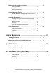
ns0814a A replacement rail kit (AR7510) of four mounting rails which accommodates 23-in rack mountable equipment in 42 U 750-mm enclosures is also available for the AR3150 and AR3350 enclosures.
Installing Equipment This section provides information on how to install rack-mount equipment in the NetShelter SX enclosure. The instructions provided with the equipment provide more detailed information. Identifying one U-space on the vertical mounting flange When installing equipment, locate the top and bottom of a U-space on the mounting flanges. Every third hole on the mounting flanges of a NetShelter enclosure is numbered to indicate the middle of a U-space.
Grounding The doors, side panels, and roof of the enclosure are grounded to the enclosure frame. The doors are grounded with quick-disconnect cables. The roof and side panels are inherently grounded through spring fingers. Each enclosure should be grounded directly to the building ground using one of the grounding nuts at the base of the enclosure. ns0905a Ground each enclosure directly to the building ground. Do not ground one enclosure to another enclosure in a cascading style.
Equipment with side airflow requirements For enclosures storing equipment that requires side airflow, the vertical mounting flange factory-installed cable cutout covers need to be removed and repositioned to the rear of the enclosure. 1. Determine which side of the enclosure is the air intake side for the equipment. 2. Remove the cable cutout covers from the front vertical mounting flange of the air intake side of the enclosure. 3.
Cable Management The NetShelter SX enclosure has multiple cable access openings, including the roof, sides, and bottom. Two vertical cable organizers are included with the enclosure, and APC offers a variety of other cable management accessories.
Cable management options for 600-mm and 750-mm enclosures Cable management rings 19-inch horizontal cable organizer 19-inch 2-U patch cord organizer 19-inch 2-U horizontal cable organizer passthrough 19-inch 1-U cable passthrough with brush strip Cable containment brackets Brush strip kit for roof Side panel with access holes 26 SKU Description AR8113A Fastens cables to posts, mounting rails, or braces. AR8426A (2U) Routes cables horizontally on the front or back of the 19-inch EIA rack.
Zero-U accessory mounting bracket Cable tree Roof bridge Vertical Cable Organizer for NetShelter 0-U Channel SKU Description AR7711 The bracket can be mounted in various locations throughout the enclosure for supporting small accessories and equipment. AR7505 Routes cables or attaches PDUs vertically in the rear of the enclosure. Consists of three pieces, including a smaller piece that allows it to be installed in a 48-U enclosure.
Vertical fiber organizer Fiber organizer (spools only) †The 28 Description AR7511 The narrow vertical cable organizer compliments the standard vertical cable organizer by offering additional cable management options. The narrow channel can be used in the front of the enclosure to mount fiber cable spools and vertical cable managers or can be used in the middle of the enclosure for cable tie off. In addition, keyholes are provided to mount one vertical Rack PDU per organizer.
Cable accessories for 750-mm enclosures Product SKU Description AR7706 Closes openings in mounting flanges to allow cable access, but maintains proper airflow. AR7707 Fastens cables to posts, for use with 750-mm enclosure networking applications. NetShelter SX air recirculation prevention kit AR7708 Maintains proper airflow if the front vertical mounting flanges are moved to the rear of the enclosure.
Joining Enclosures Joining the Enclosures You can expand your installation by joining two enclosures together. All enclosures include pre-installed joining hardware. Caution: Joining enclosures together does not provide additional stability to the enclosures. Note: NetShelter SX enclosures can be joined with or without side panels installed. 1. Remove the front doors from the enclosures if necessary. See “Removing the doors” on page 13. 2.
3. The 600-mm enclosures can be joined so that their centers are 24 in or 600 mm apart. Align the enclosures to use the appropriate holes on the front and rear of the enclosures for the spacing you need and secure the enclosures using one M5 x 12 flat-head screw per bracket. 4. If 600-mm enclosures are joined together on 24-in centers, there is a gap between them. APC offers optional baying trim (AR7600) to cover the gap between the enclosures.
Removing the Doors of Joined Enclosures If enclosures are joined together, the door removal process is slightly different than on a single enclosure. Follow these steps to remove either a front or rear door from an enclosure that is joined to another enclosure. 1. Open the door you wish to remove to a 90 degree angle. The door will not open any farther than this because of the enclosure next to it. 2. Lift the door upward. 3.
Specifications 600-mm, 42-U and 48-U Enclosures Measurements AR3100 AR3107 Height 1991 mm (78.40 in) 2258 mm (88.90 in) Width 600 mm (23.62 in) 600 mm (23.62 in) Depth 1070 mm (42.13 in) 1070 mm (42.13 in) Net weight 125.09 kg (275.20 lb) 138.23 kg (304.10 lb) Total open area (front door) 593 018 mm2 (919.18 in2) 676 805 mm² (1,049.05 in²) Total open area (rear door) 669 276 mm2 (1,037.38 in2) 763 637 mm² (1,183.64 in²) Open area per U (front door) 14 129 mm2 (21.
Measurements AR3300 AR3307 Height 1991 mm (78.40 in) 2258 mm (88.90 in) Width 600 mm (23.62 in) 600 mm (23.62 in) Depth 1200 mm (47.24 in) 1200 mm (47.24 in) Net weight 133.81 kg (295.00 lb) 149.23 kg (329.00 lb) Total open area (front door) 593 018 mm2 (919.18 in2) 676 805 mm² (1,049.05 in²) Total open area (rear door) 669 276 mm2 (1,037.38 in2) 763 637 mm² (1,183.64 in²) Open area per U (front door) 14 129 mm2 (21.90 in2) 14 103 mm² (21.
750-mm, 42-U and 48-U Enclosures Measurements AR3150 AR3157 Height 1991 mm (78.40 in) 2258 mm (88.90 in) Width 750 mm (29.53 in) 750 mm(29.53 in) Depth 1070 mm (42.13 in) 1070 mm (42.13 in) Net weight 155.95 kg (343.10 lb) 169.09 kg (372 lb) Total open area (front door) 788 972 mm2 (1,222.91 in2) 900 417 mm2 (1,395.65 in2) Total open area (rear door) 866 920 mm2 (1,343.73 in2) 989 243 mm2 (1,533.33 in2) Open area per U (front door) 18 787 mm2 (29.12 in2) 18 761 mm2 (29.
Measurements AR3350 AR3357 Height 1991 mm (78.40 in) 2258 mm (88.90 in) Width 750 mm (29.53 in) 750 mm(29.53 in) Depth 1200 mm (47.24 in) 1070 mm (42.13 in) Net weight 161.03 kg (355.00 lb) 169.09 kg (372 lb) Total open area (front door) 788 972 mm2 (1,222.91 in2) 900 417 mm2 (1,395.65 in2) Total open area (rear door) 866 920 mm2 (1,343.73 in2) 989 243 mm2 (1,533.33 in2) Open area per U (front door) 18 787 mm2 (29.12 in2) 18 761 mm2 (29.
APC Limited Factory Warranty The limited warranty provided by American Power Conversion (APC®) in this Statement of Limited Factory Warranty applies only to Products you purchase for your commercial or industrial use in the ordinary course of your business. Terms of Warranty American Power Conversion warrants its products to be free from defects in materials and workmanship for a period of five years (two years in Japan) from the date of purchase.
IN NO EVENT SHALL APC, ITS OFFICERS, DIRECTORS, AFFILIATES OR EMPLOYEES BE LIABLE FOR ANY FORM OF INDIRECT, SPECIAL, CONSEQUENTIAL OR PUNITIVE DAMAGES, ARISING OUT OF THE USE, SERVICE OR INSTALLATION, OF THE PRODUCTS, WHETHER SUCH DAMAGES ARISE IN CONTRACT OR TORT, IRRESPECTIVE OF FAULT, NEGLIGENCE OR STRICT LIABILITY OR WHETHER APC HAS BEEN ADVISED IN ADVANCE OF THE POSSIBLY OF SUCH DAMAGES.
APC Worldwide Customer Support Customer support for this or any other APC product is available at no charge in any of the following ways: • Visit the APC Web site to access documents in the APC Knowledge Base and to submit customer support requests. – www.apc.com (Corporate Headquarters) Connect to localized APC Web sites for specific countries, each of which provides customer support information. – www.apc.com/support/ Global support searching APC Knowledge Base and using e-support.