
Specifications


Rack Access PX-HID Installation 3
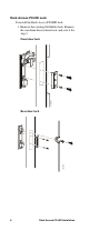
Front and Rear Panel
Components
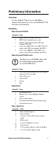
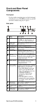
Front panel
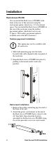
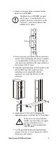
Use the toolless mounting pegs on the front panel
of the Rack Access PX-HID to install it in an APC
enclosure without using any U-spaces.
Rear panel
Item Description
AC Line Inlet Provides power to the Rack Access
PX-HID; see “Specifications” on
page 27 for voltage information.
Front Door
Lock port
Port used for communication with
the front lock.
Peripheral port Connect an optional device.
Rear Door
Lock port
Port used for communication with
the rear lock.
Power LED Indicates whether the unit is
receiving power (green–receiving
power; dark–not receiving power).
RS-232
Console Port
Serial port used to configure initial
network settings using the included
configuration cable (APC part
number 940-0103).
Reset switch Reset the Rack Access PX-HID;
this switch does not change
configuration data.
10/100 Base-T
Network Port
Connect the Rack Access PX-HID
to the network. The Status and Link
LEDs indicate network traffic.
• Status LED: Blinks orange and
green at start-up; indicates the
status of the network connection
(solid green–IP address
established; blinking green–
attempting to obtain an IP
address).
• Link LED: Blinks to indicate
network traffic (green–operating
at 10 mbps; orange–operating at
100 mbps).
Rear Door
Switch port
Port used for communication with
the rear door switch.
Alarm beacon
port
Connect an optional alarm beacon
(AP9324).
Front Door
Switch port
Port used for communication with
the front door switch.
Rear
Door
Power
AC Line In
9600- 8-N- 1
10 = G ree n
100 = Ora nge
10/ 100 B ase- T
Network Po rt
Status
Lin k
RX/TX
Reset
RS232 Con s ole P or t
Beacon
Lock
Peripheral
Switch
Front
Door
Lock
Switch
aem0108a