Installation NetBotz® Rack Access PX-HID AP9361
This manual is available in English on the APC Web site (www.apc.com). Dieses Handbuch ist in Deutsch auf der APC Webseite (www.apc.com) verfügbar. Este manual está disponible en español en la página web de APC (www.apc.com). Ce manuel est disponible en français sur le site internet d’APC (www.apc.com). Questo manuale è disponibile in italiano sul sito web di APC (www.apc.com). 本マニュアル<各国の言語に対応する>は APC ウェブサ イト (www.apc.
Contents Preliminary Information . . . . . . . . . . . . . . . . . . .1 Overview . . . . . . . . . . . . . . . . . . . . . . . . . . . . . 1 Inventory . . . . . . . . . . . . . . . . . . . . . . . . . . . . . 1 Additional options . . . . . . . . . . . . . . . . . . . . . 2 Additional documentation . . . . . . . . . . . . . . . 2 Please recycle . . . . . . . . . . . . . . . . . . . . . . . . 2 Receiving inspection . . . . . . . . . . . . . . . . . . . 2 InfraStruXure-certified . . . . . . . . . . . . . . .
Upgrading Firmware. . . . . . . . . . . . . . . . . . . . 24 Automated upgrade tool for Microsoft Windows systems . . . . . . . . . . . . . . . . . . . . .24 Manual upgrades, primarily for Linux systems . . . . . . . . . . . . . . . . . . . . . . . .24 Firmware file transfer methods . . . . . . . . . .25 Use FTP to upgrade one Rack Access PX-HID . . . . . . . . . . . . . . . . . . . . . . . .25 Use XMODEM to upgrade one Rack Access PX-HID . . . . . . . . . . . . . . . . . . . . . . . .25 Specifications . .
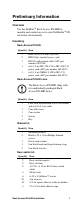
Preliminary Information Overview Use the NetBotz® Rack Access PX-HID to monitor and control access to your NetShelter® SX enclosure electronically. Inventory Rack Access PX-HID. Quantity Item 1 2 1 1 1 Rack Access PX-HID (AP9361) HID 26-bit standard access cards RS232 configuration cable (APC part number 940-0103) 6-ft (1.8-m) IEC-320-C13 to IEC-320-C14 power cord (APC part number 960-0007) 6-ft (1.8-m) NEMA 5-15P to IEC-C13 power cord (APC part number 960-0079) Rack Access PX-HID Lock.
Quick-disconnect kit.
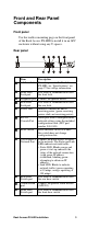
Front and Rear Panel Components Front panel Use the toolless mounting pegs on the front panel of the Rack Access PX-HID to install it in an APC enclosure without using any U-spaces.
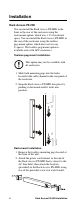
Installation Rack Access PX-HID You can install the Rack Access PX-HID in the front or the rear of the enclosure using the rack-mount option, which uses 1 U of enclosure space. You can install the Rack Access PX-HID in the rear of the enclosure using the toolless peg-mount option, which does not use any U-spaces. The toolless peg-mount option is available only with APC enclosures. Toolless peg-mount installation. This option may not be available with all enclosures. 1.
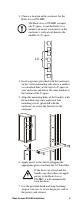
3. Choose a location in the enclosure for the Rack Access PX-HID. The Rack Access PX-HID occupies one U-space. A notched hole (or a number, on newer enclosures) on the enclosure’s vertical rail denotes the middle of a U-space. 7 6 5 ns0014a 1U pdu0080a 4. Insert cage nuts (provided with the enclosure) on the vertical mounting rails above a number (or a notched hole) at the top of a U-space in your enclosure and below the same number at the bottom of the U-space. 5.
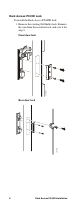
Rack Access PX-HID Lock To install the Rack Access PX-HID lock: 1. Remove the existing NetShelter lock. Remove the cam from the rear door lock, and save it for step 3.
2. Install the Rack Access PX-HID lock. aem0093a a. Slide the Rack Access PX-HID lock through the opening in the enclosure door where the original lock was located. aem0091a b. Place the rear cover on the lock and insert the screws to secure the lock in place.
3. Install the cam washer and cam on the Rack Access PX-HID lock. For the rear lock, use the cam removed in step 1. aem0090a Front door lock aem0095a Rear door lock 4. Route the lock cord. 5. At the hinge between the door and the rack, connect the sensor cord to an RJ-45/RJ-45 coupling. Connect a 10-ft black CAT5 cable (provided) to the other side of the coupling. aem0096a 6. Continue routing the cord, and connect the cord to the appropriate Door Lock port.
Installation—Accessories Door switch Doors with Rack Access PX-HID locks must have door switches. 1. Choose a location at the top of the enclosure to install the door switch and door switch magnet. aem0080a Front door: Install the front door switch and front door switch magnet perpendicular to the floor. aem0181a Rear door: Install the rear door switch and rear door switch magnet parallel to the floor. 2. Connect the door switches to the enclosure frame. a.
a e m0 0 9 7 a d. Place the plastic cover over the door switch and snap the cover into place. Route the cable out the opening in the cover. e. Plug the door switch cables into the ports marked Front Door Switch and Rear Door Switch on the rear panel of the Rack Access PX-HID. 3. Connect the door switch magnet to the enclosure door. Do not place the plastic cover over the door switch magnet until the door switch has been installed on the enclosure door. Front door a.
Alarm beacon (optional) 1. Install the alarm beacon in a visible position either on the roof of the enclosure or inside the enclosure. The beacon has a magnetic base. aem0061a 2. If you install the beacon on the roof, route its cable through the provided holes, as shown in the following illustration. 3. Plug the cable into the Beacon port. 4. You can extend the cable to a maximum of 330 ft (100 m), using RJ-45 couplings and standard CAT5 cables.
Quick Configuration If you are managing the Rack Access PX-HID on the APC LAN of an InfraStruXure Manager Server, Rack Access PX-HID network and NTP settings will be automatically configured by the BOOTP server of the InfraStruXure Manager Server. If, however, you want the Rack Access PX-HID to be accessible on the User LAN (your corporate network), you must configure the Rack Access PX-HID in the manner described in this section.
APC Device IP Configuration Wizard You can use the APC Device IP Configuration Wizard at a Windows® 2000, Windows Server 2003, or Windows XP computer to configure the basic TCP/IP settings of the Rack Access PX-HID. To configure multiple Rack Access PX-HIDs, or to configure a Rack Access PX-HID from a user configuration file, see the Rack Access PX-HID User’s Guide, available on the enclosed Utility CD. 1. Insert the Utility CD into a computer on your network. 2.
The default setting, BOOTP & DHCP, causes the Rack Access PX-HID to attempt to discover a properly configured server. It first searches for a BOOTP server, then a DHCP server, and repeats this pattern until it discovers a BOOTP or DHCP server. For more information, see “BOOTP” on page 14 or “DHCP” on page 15. BOOTP. You can use an RFC951-compliant BOOTP server to configure the TCP/IP settings for the Rack Access PX-HID.
DHCP. You can use a RFC2131/ RFC2132-compliant DHCP server to configure the TCP/IP settings for the Rack Access PX-HID. This section briefly summarizes the Rack Access PX-HID communication with a DHCP server. For more detail about how a DHCP server is used to configure the network settings for the Rack Access PX-HID, see “DHCP Configuration” in the Rack Access PX-HID User’s Guide. 1.
Local access to the control console You can use a local computer that connects to the Rack Access PX-HID through the serial port on the rear of the unit to access the control console. 1. Select a serial port at the local computer, and disable any service that uses that port. 2. Use the configuration cable (APC part number 940-0103) to connect the selected port to the serial port on the rear panel of the Rack Access PX-HID. 3.
2. Use Ping with a size of 113 bytes to assign the IP address defined by the ARP command. For the IP address defined in step 1, use one of the following Ping commands: Windows command format: ping 156.205.14.141 -l 113 LINUX command format: ping 156.205.14.141 -s 113 3. Use Telnet to log on to the Rack Access PX-HID at its newly assigned IP address. For example: telnet 156.205.14.141 4. Use apc for both User Name and Password. See “Control console” on page 17 to finish the configuration.
Accessing a Configured Unit Log on to the configured Rack Access PX-HID through the following interfaces: • Web interface (HTTP or HTTPS protocol) • Telnet or Secure SHell (SSH) • SNMP • FTP or Secure CoPy (SCP) to upgrade firmware For more information on the interfaces, see the Rack Access PX-HID User’s Guide. Web interface As your Web browser, you can use Microsoft® Internet Explorer® 5.5 and higher (on Windows operating systems only), Firefox, version 1.
See the Security Handbook for information on choosing and setting up your network security. On the Administration tab, select the Network option on the top menu bar, then the access option under Web on the left navigation menu to enable or disable the HTTP or HTTPS protocols. Telnet You can access the control console through Telnet or Secure SHell (SSH), depending on which is enabled.
SNMP After you add the PowerNet MIB to a standard SNMP MIB browser, you can use that browser for SNMP access to the Rack Access PX-HID. The default read community name is public; the default read/write community name is private. If you enable SSL and SSH for their high-security authentication and encryption, disable SNMP. Allowing SNMP access to the Rack Access PX-HID compromises the high security you implement by choosing SSL and SSH. To disable SNMP, you must be an Administrator.
Configuring an Access Card To configure an access card, you must be able to view the Web interface or control console of the Rack Access PX-HID. See “Quick Configuration” on page 12 for configuration information. See “Accessing a Configured Unit” on page 18 for information about accessing the Web interface or control console. Web interface 1. Log in at the Web interface. Click the Rack Access tab. 2. Select the left navigation menu item Door Properties, select the card format, then log off.
9. Enable the card user’s access for specific days of the week and for a period of time on each of those days. a. To enable access on a day, mark the checkbox next to the day. b. To specify the time period during which the card can unlock the rack on a selected day, enter the time in hours and minutes. Valid times are 00:00 to 23:59. 10. Click Register User to apply the configuration settings for the card. Control console 1. Log in at the control console. Select Device Manager, then Door Properties.
Recovering from a Lost Password You can use a local computer or a computer that connects to the Rack Access PX-HID through the serial port to access the control console. 1. Select a serial port at the local computer, and disable any service that uses that port. 2. Connect the serial cable (APC part number 940-0103) to the selected port on the computer and to the RS-232 console port at the Rack Access PX-HID. 3.
Upgrading Firmware Automated upgrade tool for Microsoft Windows systems An automated, self-extracting executable tool combines the firmware modules that you need to automate your upgrades on any supported Windows operating system. You can obtain the current version of the tool at no cost from the support section of the APC Web site, www.apc.com/tools/download. At this Web page, find the latest firmware release for your APC product and download the automated tool, not the individual firmware modules.
Firmware file transfer methods To upgrade the firmware of the Rack Access PX-HID: • From a networked computer running a Microsoft Windows operating system, you can use the automated firmware upgrade tool downloaded from the APC Web site, www.apc.com/tools/download. • From a networked computer on any supported operating system, you can use FTP or SCP to transfer the individual AOS and application firmware modules.
5. Enter your User Name and Password (both apc, for administrators only) and press the ENTER key. 6. From the Control Console menu, select System, then Tools, then File Transfer, then XMODEM. 7. The system will prompt you with Perform transfer with XMODEM -CRC? Type Yes and press ENTER. 8. The system will then prompt you to choose a transfer rate and to change your terminal settings to match the transfer rate. Press ENTER to set the Rack Access PX-HID to accept the download. 9.
Specifications Rack Access PX-HID Electrical Input voltage, nominal 100–240 VAC; 50/60 Hz Physical Dimensions (H × W × D) Weight Shipping weight Shipping dimensions (H × W × D) 1.74 × 17.00 × 1.74 in (4.42 × 43.20 × 4.42 cm) 2.20 lb (0.99 kg) 8.15 lb (3.69 kg) 2.62 in × 17.75 × 8.87 in (6.70 × 45.00 × 22.
Two-Year Factory Warranty This warranty applies only to the products you purchase for your use in accordance with this manual. Terms of warranty APC warrants its products to be free from defects in materials and workmanship for a period of two years from the date of purchase. APC will repair or replace defective products covered by this warranty. This warranty does not apply to equipment that has been damaged by accident, negligence or misapplication or has been altered or modified in any way.
LIABILITY WILL ARISE OUT OF, APC RENDERING OF TECHNICAL OR OTHER ADVICE OR SERVICE IN CONNECTION WITH THE PRODUCTS. THE FOREGOING WARRANTIES AND REMEDIES ARE EXCLUSIVE AND IN LIEU OF ALL OTHER WARRANTIES AND REMEDIES. THE WARRANTIES SET FORTH ABOVE CONSTITUTE APC’S SOLE LIABILITY AND PURCHASER’S EXCLUSIVE REMEDY FOR ANY BREACH OF SUCH WARRANTIES. APC WARRANTIES EXTEND ONLY TO PURCHASER AND ARE NOT EXTENDED TO ANY THIRD PARTIES.
Life-Support Policy General policy American Power Conversion (APC) does not recommend the use of any of its products in the following situations: • In life-support applications where failure or malfunction of the APC product can be reasonably expected to cause failure of the life-support device or to affect significantly its safety or effectiveness. • In direct patient care.
Radio Frequency Interference Changes or modifications to this unit not expressly approved by the party Warning responsible for compliance could void the user’s authority to operate this equipment. USA—FCC This equipment has been tested and found to comply with the limits for a Class A digital device, pursuant to part 15 of the FCC Rules. These limits are designed to provide reasonable protection against harmful interference when the equipment is operated in a commercial environment.
Australia and New Zealand Attention: This is a Class A product. In a domestic environment this product may cause radio interference in which case the user may be required to take adequate measures. European Union This product is in conformity with the protection requirements of EU Council Directive 89/336/EEC on the approximation of the laws of the Member States relating to electromagnetic compatibility.
APC Worldwide Customer Support Customer support for this or any other APC product is available at no charge in any of the following ways: • Visit the APC Web site to access documents in the APC Knowledge Base and to submit customer support requests. – www.apc.com (Corporate Headquarters) Connect to localized APC Web sites for specific countries, each of which provides customer support information. – www.apc.com/support/ Global support searching APC Knowledge Base and using e-support.