
Specifications
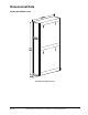
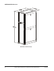
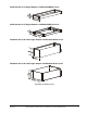

38 InRow™ Direct Expansion Air Conditioners Technical Specifications 990-4617
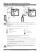
Piping and Mechanical Connections
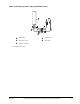
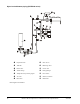
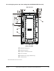
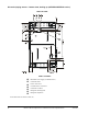
Refrigeration piping diagram (ACRD100/ACRD500/ACRP100 series))
Note: Shutoff valves shown nearest to the condensers are not supplied by APC by Schneider
Electric.
ACRD500/ACRP100 series: The shutoff valves nearest to the cooling unit are supplied by APC by
Schneider Electric.
ACRD100 series: The shutoff valves are not supplied and must be ordered.
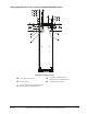
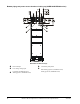
• Route piping through the top or bottom of the InRow ACRD/ACRP series.
• All lines are Type L ACR copper tubing.
• Trap the vertical discharge line every 6 m (20 ft) to ensure proper oil return.
• Pipe size should change after the P-trap based on the recommended piping charts provided with
the installation manual.
• For the ACRD500/ACRP100 series, the maximum piping run is 61 m (200 ft) equivalent length.
Size the piping pursuant to accepted refrigeration practice.
• Fore the ACRD100 series, piping is 46m (150 ft) equivalent length. Size the piping pursuant to
accepted refrigeration practices.
Warning: Do not install the air-cooled condenser below the InRow ACRD/ACRP series. The
condenser must be positioned above or at the same level as the InRow ACRD/ACRP series to
ensure proper function.
Pitch in direction of refrigerant flow; 4 mm per m
(1/2 in per 10 ft)
P-trap
Shutoff valves S-trap
Head pressure control valve Inverted P-trap
Check valve Pressure relief valve
H
o
t
g
a
s
L
i
q
u
i
d
H
o
t
g
a
s
RD/RP
RD/RP
Receiver Receiver
Bottom piping
Top piping
Condenser Condenser
L
i
q
u
i
d