Installation and Start-Up 60kW InfraStruXureTM System Large Data Centers 208/480/600 V Input
08/480/600V
About this Manual This manual is intended for APC Field Service Engineers or APC-trained installers of a 60kW InfraStruXure system. It covers basic installation and start-up. For information about installing specific components in your InfraStruXure system, see the documentation included with each component. Before installing or operating any component, refer to the safety instructions in the component’s manual.
Contents Safety ......................................................................1 Overview . . . . . . . . . . . . . . . . . . . . . . . . . . . . . . . . . . . . . . . . . 1 Save these instructions . . . . . . . . . . . . . . . . . . . . . . . . . . . . 1 Safety symbols used in this manual . . . . . . . . . . . . . . . . . . . 1 Cross-reference symbols used in this manual . . . . . . . . . . . . . 1 Warnings . . . . . . . . . . . . . . . . . . . . . . . . . . . . . . . . . . . . . . . . .
Route the input conductors to the Main Input circuit breaker (or switch) . . . . . . . . . . . . . . . . . 16 Torque specs and tools required . . . . . . . . . . . . . . . . . . . . 16 Connect input conductors . . . . . . . . . . . . . . . . . . . . . . . . 17 Connect an Emergency Power Off Switch . . . . . . . . . . . . . . . . 18 Overview . . . . . . . . . . . . . . . . . . . . . . . . . . . . . . . . . . . . 18 Connect an EPO switch to the user connection plate and test the switch . . . . . . . . . . .
Appendix A: Operation ..........................................37 How to Apply Power to the System . . . . . . . . . . . . . . . . . . . . . 37 How to Ensure Total Power Off . . . . . . . . . . . . . . . . . . . . . . . 39 Appendix B: Changes in this Manual ......................
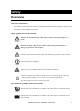
Safety Overview Save these instructions This manual contains important instructions that must be followed during installation, operation, and maintenance of the InfraStruXure System. Safety symbols used in this manual Electrical Hazard Indicates an electrical hazard, which, if not avoided, could result in injury or death. Indicates a hazard, which, if not avoided, could result in personal injury or damage to product or other property.
Warnings Receiving/moving Do not tilt the PDU greater than 45° from its vertical axis. Never lay the PDU on its side. Installation/Maintenance Only a certified electrician can: • Connect the PDU to its power source • Connect a switch to the EPO interface on the PDU • Install a customer-specified, hard-wired power cable Only a certified electrician or an APC Field Service Engineer can perform maintenance of the PDU.
Safety: Warnings Total Power Off 1. Set the PDU Main Input to OFF. 2. Set the upstream power source feeding the PDU to OFF. Emergency Power Off (EPO) Hazardous voltage from the branch circuit must be isolated from the 24VAC, 24VDC, and contact closure. 24VAC and 24VDC are considered Class 2 circuits as defined in Article 725 of the National Electrical Code (NFPA 70) and Section 16 of the Canadian Electrical Code (C22.1).
Site Planning Dimensions InfraStruXure PDU Without PDU Shielding Trough: 81.5in (2070mm) PDU Shielding Trough Including PDU Shielding Trough: 88.8in (2255mm) 23in (584mm) 23.5in (597mm) 7.2in (183mm) 34.5in (876mm) NetShelter VX Enclosure 23.5in (597mm) Shielding Partitions 23.5in (597mm) 4.8in (122mm) 81.5in (2070mm) 7.2in 23.5in (183mm) (597mm) 42.
Space Considerations Study the figure below to determine your space requirements for installing the InfraStruXure PDU. Consult your local codes and the NEC for additional requirements.
Weight Considerations Ensure that the floor and sub-floor can support the total weight of the configuration when concentrated on the leveling feet. If you are placing equipment on a raised floor, consult the flooring manufacturer for loading requirements before installing equipment.
Heat Output Consider the heat dissipation ratings of equipment to determine cooling requirements. Additional cooling equipment may be required. Heat output of the InfraStruXure PDU is shown below. Voltage InfraStruXure PDU with a transformer 208V input 7169 BTU/hr (2.10kW) 480V input 7412 BTU/hr (2.17kW) 600V input 4894 BTU/hr (1.43kW) The heat output is higher while batteries are charging. Under normal operating conditions, battery recharging periods are infrequent.
Electrical Requirements and Specifications Procedures requiring a licensed electrician Procedures requiring a licensed electrician include: • Connection of utility conductors Electrical Hazard • Installation of a 225-, 90-, or 75-amp circuit breaker • Connection to the Main Input switch • Wiring under the floor To connect utility conductors, see Certified Electrician’s Instructions included with your PDU documentation.
Emergency Power Off (EPO) Overview To provide a mechanism for emergency power off, attach a remote switch to the EPO interface on the PDU monitoring unit through the user connection plate. The EPO interface () is connected to the PDU Main Input switch () and to the UPS internal EPO switch (). Sw itch PDU UPS When the EPO is activated, the main input breaker to the PDU transformer is opened, the UPS DC Disconnect breaker is opened, and the UPS System Enable switch is turned off.
Basic Installation Procedure This section provides the basic steps that you need to perform when installing InfraStruXure power and rack components. Follow the references provided with each step for detailed instructions. Do not begin installing your InfraStruXure system without an APC Field Service Engineer present. Warning 1. Unpack the components according to the unpacking instructions included on the outside of the packaging or in the component’s manual.
Site Planning: Basic Installation Procedure 8. Install Shielding Troughs, Shielding Partitions, and Cable Ladders. For instructions, see the manuals included with your Shielding Troughs, Shielding Partitions, and Cable Ladders. See also 9. Install the Rack Automatic Transfer Switches (ATS), Rack Power Distribution Units, and other InfraStruXure rack-mount devices. For instructions, see the manuals included with your Rack ATS, Rack PDU, or other InfraStruXure rack-mount device. See also 10.
Installation Procedures Level the PDU and NetShelter Enclosures Leveling feet are attached under the enclosure at each corner. The leveling feet can help provide a stable base if the selected floor space is uneven, but they are not intended to compensate for a badly sloped surface. To level the enclosure: 1. Fit the 14-millimeter end of the open-ended wrench (provided) to the hex head just above the round pad on the bottom of the leveling foot.
Connect the Power Source to the PDU Access the PDU Main Input switch Open the back doors of the PDU, unlock the top, smaller door, using the provided red key, and loosen the two screws holding the larger, hinged door in place. Attach conduit to the PDU for the input conductors 1.
Installation Procedures: Connect the Power Source to the PDU – In the top of the PDU for overhead wiring 2. Cut an appropriately-sized hole in the gland plate for the conduit. 3. Re-attach the gland plate. 4. Install a lock-nut and bushing to the conduit. 5. Thread the conduit through the hole.
Installation Procedures: Connect the Power Source to the PDU Install a circuit breaker Make sure the cables used for power input are sufficiently protected by a circuit breaker. Warning Determine the amperage of circuit breaker that you need to install: Input Voltage Circuit Breaker Amperage 208V 225A 480V 90A 600V 75A Route the input conductors to the Main Input circuit breaker (or switch) 1.
Installation Procedures: Connect the Power Source to the PDU Connect input conductors A licensed electrician must connect input conductors to the PDU. Electrical Hazard At the Main Input circuit breaker (or switch), connect the input wiring according to the labels on the circuit breaker (or switch) and the illustrations below. See the table, “Torque specs and tools required” on page 16 for specific information about connecting to each terminal.
Connect an Emergency Power Off Switch Overview Connecting the switch. The Emergency 4 Contact Outputs ATS 1 2 3 Contact Inputs ATS 2 1 ATS 0 USER INTERFACE © 2001 APC MADE IN USA ATS EN Power Off (EPO) switch connects to the PDU user connection plate. The figure on the right shows the location of the user connection plate on the roof of the PDU.
Installation Procedures: Connect an Emergency Power Off Switch Connect an EPO switch to the user connection plate and test the switch 1. Connect the switch to the EPO connection point terminals located on the bottom side of the PDU user connection plate.
Installation Procedures: Connect an Emergency Power Off Switch 3. Test the EPO switch to ensure that it is wired and working correctly: a. Place the Arm/Test rocker switch in the Test position. The EPO state LEDs will be off and the PDU display interface will show the following alarm (in addition to any other active alarms): Active Alarm xxofxx EPO Ready To Test b. Engage the EPO switch. (If your switch is momentary, engage it with one person watching the EPO state LEDs, and another at the EPO switch.) c.
Installation Procedures: Connect an Emergency Power Off Switch Safety warnings Hazardous voltage from the branch circuit must be isolated from the 24VAC, 24VDC, and contact closure. 24VAC and 24VDC are considered Class 2 circuits as defined in Article 725 of the National Electrical Code (NFPA 70) and Section 16 of the Canadian Electrical Code (C22.1). A Class 2 circuit is a source having limited voltage and energy capacity as follows: a.
Connect User Input Contacts and Relay Outputs to the User Connection Plate Overview 4 Contact Outputs ATS 1 2 3 Contact Inputs ATS 2 1 ATS 0 USER INTERFACE © 2001 APC MADE IN USA ATS EN Make contact closure connections (NO or NC) at the user connection plate to monitor dry contacts. You can make eight connections—four input contacts and four relay outputs. – + EPO 24V EPO AC/DC Contact The figure at the right shows the location of the user connection plate on the roof of the PDU enclosure.
Installation Procedures: Connect User Input Contacts and Relay Outputs How to connect contacts to the PDU Monitoring Unit 1. Choose one or more contact numbers on the user connection plate to which you will connect the contacts. The user connection plate is connected to the User/EPO port on the PDU monitoring unit. 2. From the PDU display interface: a. Press the ESC or ENTER key to go to the top-level menu screen. b. Select Contacts on the top-level menu screen and press the ENTER key. c.
Install Shielding Troughs, Shielding Partitions, and Cable Ladders Shielding Troughs and Shielding Partitions for overhead wiring along rows If you ordered APC Shielding Troughs, Shielding Partitions, and Cable Ladders to route overhead wiring for your system, assemble the Shielding Troughs and the Shielding Partitions along the rows of enclosures and assemble the Cable Ladders between rows See also For detailed installation and grounding instructions, see the instruction sheet included with the Shielding
Installation Procedures: Install Shielding Troughs, Shielding Partitions, Shielding Partitions. There are two types of Shielding Partitions, each of which forms a side wall of a trough for data cables. You can customize the width of the trough for each row of your system — wider for rows carrying many data cables, narrower for rows carrying fewer. • As the back wall, use a Shielding Partition that contains an opening for routing data cables.
Install InfraStruXure Rack-Mount Devices Install the Rack Automatic Transfer Switches (ATS) Install a Rack ATS in the top of each enclosure for overhead wiring, and in the bottom of each enclosure for wiring under the floor. See the installation instructions in the manual included with your Rack ATS. See also The Rack ATS is an optional component and not all InfraStruXure systems will include them.
Route and Attach Overhead Wiring Route and attach power cables to equipment racks If you ordered overhead wiring, connect the prewired power cables of the PDU as follows: 1. Install the Shielding Troughs, Shielding Partitions, and Cable Ladders so that you can route power cables from the PDU to the NetShelter VX Enclosures. For installation instructions, see the manual included with your Shielding Troughs, Shielding Partitions, and Cable Ladders. See also 2.
Installation Procedures: Route and Attach Overhead Wiring – For dual-feed devices within a redundant system: attach a power cable from each PDUto two different Rack PDUs in the NetShelter VX Enclosure. – For single-feed devices within a redundant system with an Automatic Transfer Switch: connect a power cable to the Automatic Transfer Switch (A and B feeds) and connect the Automatic Transfer Switch power cord to a Rack PDU in the NetShelter VX Enclosure.
Installation Procedures: Route and Attach Overhead Wiring 5. From each NetShelter VX Enclosure, run the power cable of the appropriate APC power management device out the roof of the enclosure, through the notch in the rear side of the Shielding Trough, to the connector of the appropriate power cable from the PDU. Plug the two connectors together, and twist them clockwise to lock.
Wiring Under the Floor Electrical Hazard A licensed electrician must route and connect the power cables for under-floor wiring. Make sure all wire connections and circuit breaker connections are properly torqued. Warning If you are routing power cables to the enclosures under a raised floor, you must provide the appropriate power cables and equipment for installation, and a licensed electrician must route and connect the power cables to the PDU circuit breakers.
Installation Procedures: Wiring Under the Floor 5. At the circuit breaker panel, cut the wires to the proper length, and connect the power cable’s individual wires: a. If you have branch current monitoring installed, route each phase conductor through a current sensor. If it is a three-phase cable, route the L1, L2, and L3 wires through a separate current sensor. b. Connect the L1, L2, and L3 wires to the circuit breaker(s).
Route Data Cables to the InfraStruXure Manager Hub (or Switch) 1. Connect a Cat-5 network cable (provided) to the network or 10Base-T ports on your APC InfraStruXure devices.
Start-Up Procedure Safety warnings This section provides instructions on how to perform a system start-up. Do not skip any steps in this procedure. Electrical Hazard Electrical Hazard Only APC Field Service Engineers or qualified, APC-trained personnel may perform a system start-up. Before you proceed, ensure that power is off by following the procedure in this section. Ensure that all power is off 1. Set the PDU Main Input to OFF. 2.
Start-Up Procedure: InfraStruXure System Apply power to the system 1. Set the upstream input circuit breaker (utility or UPS) to ON. 2. Ensure A-B-C clockwise phase rotation at the top of the Main Input on the PDU, using a phase rotation meter. 3. Set the Main Input on the PDU to ON. 4. Verify A-B-C clockwise phase rotation at the top of the primary winding of the transformer, using a phase rotation meter. 5.
Start-Up Procedure: InfraStruXure System 6. If applicable, set the Main Output circuit breaker on the PDU to ON. When the Main Output circuit breaker is closed, the power distribution circuit breaker panels are energized. Note 7. Close (turn ON) the PDU distribution panel circuit breakers. When the distribution panel circuit breakers are closed, the PDU power cables and connected equipment are energized.
Configure the InfraStruXure Manager Once all equipment is installed, the network cables are connected to the InfraStruXure Manager hub (or switch), and start-up of the system is complete, configure the InfraStruXure Manager. For instructions, see the InfraStruXure Manager Installation and Quick-Start manual included with your InfraStruXure Manager.
Appendix A: Operation How to Apply Power to the System This procedure instructs on how to apply power to a system that has already been installed. For initial start-up instructions, see the Start-up section of this manual. 1. Close (turn ON) the main circuit breaker of the power source supplying power to the PDU. 2. Set the Main Input on the PDU to ON. 3. Power the PDU distribution circuit breakers: a. For PDU with transformer: Set the Main Output circuit breaker on the PDU to ON.
Appendix A: Operation b. For PDUs with and without a transformer: Close (turn On) the PDU distribution panel circuit breakers. When the distribution panel circuit breakers are closed, the PDU power cables and connected equipment are energized.
How to Ensure Total Power Off 1. Open (turn OFF) the main circuit breaker on the power source feeding the PDU. 2. Set the Main Input on the PDU to OFF. 3. For PDU with transformer: Set the Main Output circuit breaker on the front of the PDU to OFF.
Appendix B: Changes in This Manual Overview The following list references the specific changes made to this manual since its last release (9901638A). General changes An index was added to the end of this manual. See pages 43–44. Changes by page number Pages 18–21 Updated section on connecting the EPO switch to the user connection plate. Pages 22–23 Replaced “Connect User Contacts to the PDU Monitoring Unit” with “Connect User Input Contacts and Relay Outputs to the User Connection Plate.
Index A automatic transfer switch, installing, 25 C cable ladders, installing, 24 circuit breaker size, determining by input voltage, 2 E electrical requirements, 9 Emergency Power Off (EPO) connect the switch, 18 – 20 overview, 10 troubleshooting problems with, 19 warnings, 3, 20 EMI warnings, 3 Environmental Management System installing, 25 Environmental Monitoring Unit, installing, 25 EPO. See Emergency Power Off (EPO).
T tools required, 16 torque specifications, 16 total power off ensuring, 33, 39 warnings, 3 U updates in this manual, 41 to this manual, i W warnings, 2 – 3 Emergency Power Off (EPO), 3 EMI, 3 for maintenance while the PDU is receiving power, 2 installation/maintenance, 2 receiving/moving, 2 total power off, 3 weight considerations, 7 wiring route and attach overhead, 26 – 28 under the floor, 29 – 30 44 InfraStruXure System—Installation and Start-Up
APC Worldwide Customer Support Customer support for this or any other APC product is available at no charge in any of the following ways: • Visit the APC Web site to access documents in the APC Knowledge Base and to submit customer support requests. – www.apc.com (Corporate Headquarters) Connect to localized APC Web sites for specific countries, each of which provides customer support information. – www.apc.com/support/ Global support searching APC Knowledge Base and using e-support.