InfraStruXure™ InRow SC Air-Cooled Self-Contained- 50/60Hz Technical Data
Contents Overview . . . . . . . . . . . . . . . . . . . . . . . . . . . . . . . . . . . . . . . . . . . . . . . . 1 InRow SC System Overview . . . . . . . . . . . . . . . . . . . . . . . . . . . . . . . . 2 Application Guidelines . . . . . . . . . . . . . . . . . . . . . . . . . . . . . . . . . . . . 3 Standard Features . . . . . . . . . . . . . . . . . . . . . . . . . . . . . . . . . . . . . . . . 4 Optional Features . . . . . . . . . . . . . . . . . . . . . . . . . . . . . . . . . . . . . . . . .
ii
Overview The InRow SC offers efficient, effective and economical cooling for a variety of wiring closets and server room spaces. • Computer rooms • Wiring Closets • Telecommunication facilities • Power equipment • Medical equipment rooms • LAN/WAN environments A worldwide network of APC representatives is fully qualified to provide engineering, sales, installation and service for our products. APC warrants all parts for 12 months from date of shipment. Extended warranties are available.
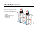
InRow SC System Overview InRow SC System Overview Self Contained System An air-cooled self-contained system has all the refrigerant system components located in a single enclosure. The unit is pre-charged from the factory and requires no field installed refrigerant lines or remote heat exchangers. Heat is rejected to a building return plenum via the ducting kit designed to connect to a standard drop ceiling.
Application Guidelines Application Guidelines Self-Contained System The InfraStruXure InRow SC self-contained unit is designed to be placed in-row, between equipment racks for cooling-only applications. The unit has a nominal cooling capacity of 5kW and is intended to provide dedicated cooling for wiring closets, server rooms and small data centers that have a drop ceiling as part of the building return plenum. The unit is designed for very high sensible heat ratio cooling.
Standard Features Variable Speed Direct Drive Tubeaxial Fans Each unit is equipped with six 200mm mixed flow, direct drive, tubeaxial DC fans. Three of the fans blow air across the condenser coil to provide heat rejection from the refrigerant system. In order to provide uniform airflow across the evaporator coil, the remaining three fans draw air through the evaporator section. The evaporator fans can be easily replaced while the unit is in operation.
Optional Features Rope Water Detectors The solid-state spot water detector activates an audible alarm on the controller when moisture is detected, providing protection along a 20ft (6.1m) length. A maximum of four detectors can be installed in series, for a total of 80ft (24.4m). Cable Support Bridge Trough Organizes cables over the top of the unit without interfering with the duct tubes.
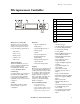
Microprocessor Controller Microprocessor Controller X Y Z [ \ ] ^ _ ` Microprocessor Controller The microprocessor controller is standard on each system. The controller provides precision control for the demanding requirements of: • Data centers • Server rooms • Wiring closets • Switch rooms • UPS rooms Open Architecture The NetworkAIR SC protocol is open for integration with all building management systems. Communication interface on the system is MODBUS RS485.
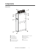
Components na2229a External View Intake Air Duct Adjustable Leveling Foot (4 places) Removable Rear Door Display Interface Side Panel Latch/Lock Removable Front Door Removable Side Panel Door Lock Rear Casters (Non-swiveling) Exhaust Air Duct Front Casters (Swiveling) APC InRow SC Technical Data Manual 7
Components na2219a Internal View Condenser Coil Refrigeration Filter Drier Condenser Fans Hot Gas Bypass Valve Compressor Power Supply Condensate Pan Floats Condensate Pump Evaporator Fans High Voltage Box Evaporator Coil Thermostatic Expansion Valve 8 Washable 1/2in Air Filter ! User Interface Box APC InRow SC Technical Data Manual
Air-cooled Performance Specifications NET COOLING CAPACITY Model ACSC100 ACSC101 200-240V, 1ph, 60Hz 200-240V, 1ph, 50Hz Total - BTU/hr (Watts) 16300 (4770) 15100 (4410) Sensible - BTU/hr (Watts) 15100 (4440) 14300 (4200) Total - BTU/hr (Watts) 17000 (4980) 15400 (4510) Sensible - BTU/hr (Watts) 15500 (4530) 14400 (4230) Total - BTU/hr (Watts) 16700 (4890) 16200 (4740) Sensible - BTU/hr (Watts) 16200 (4740) 15900 (4650) Total - BTU/hr (Watts) 18100 (5310) 18000 (5250) Sensible - BT
General Technical Specifications MODEL ELECTRICAL INPUT AIR SYSTEM - Direct Drive Tubeaxial Fans* Maximum Evaporator Airflow - CFM (m3/hr) Minimum Evaporator Airflow - CFM (m3/hr) Maximum Condenser Airflow - CFM (m3/hr) Minimum Condenser Airflow - CFM (m3/hr) REFRIGERANT R410A - oz (kg) Maximum Total Heat of Rejection BTU/hr (Watts) EVAPORATOR COIL - COPPER TUBE/ALUMINUM FIN ACSC100 ACSC101 200-240V, 1ph, 60Hz 200-240V, 1ph, 50Hz Face Area - ft2 (m2) Rows Deep Face Velocity - FPM (m/s) FILTERS Quantity Si
Electrical Data Electrical Data Rated SKU In-Rush*** Phase Frequency (Hz) Current* (Amps) Power** (Watts) Power Factor Duration (ms) Peak Current (Amps) Power (Watts) 208-230 1 60 16.0 2940 0.98 200 56.0 8240 220-240 1 50 14.4 2390 0.98 60 65.
Sound Performance Data Sound Performance Data Air-Cooled Tested Sound Data Fan Speed% Evaporator Air-flow Rate (SCFM) Octave Band Hz, Sound Power dB re 10-12Watts. Data obtained from Reverberation Sound Tests in accordance with ANSI S12.51-2202, ISO 3741-1999 125 250 500 1000 2000 4000 8000 Sound Power (dBA) Lp Sound Pressure dB re: 20 microPa* dBA EvF 100% CondF 100% 1180 77.5 86.5 86.5 83.0 78.0 75.5 70.5 87.7 82.2 EvF 90% CondF 100% 1080 77.5 86.5 85.5 81.0 76.0 73.5 68.
Dimensional Data na2231a InRow SC Assembled Module Dimensions are inches (millimeters) APC InRow SC Technical Data Manual 13
Mechanical Connections Mechanical Connections InRow SC Condensate Line and Power Connections Dimensions are inches (millimeters) Note: For more detailed information, please refer to submittal drawings 14 APC InRow SC Technical Data Manual
Guidelines for Installation The InRow SC provides reliable, self-contained cooling that maximizes availability within small IT rooms and wiring closets. The unit incorporates the latest system design innovations to provide you with optimum efficiency, reliability and rapid installation. For more detailed information, see the InRow SC Installation manual (990-2796).
Guidelines for Installation Service Access n a2 23 0 a Routine service and basic repair activities can be accomplished with front and rear access only. APC recommends 36ft (914mm) of clear floor space in front and back of the unit for this purpose. For major repair activities needing side access, 30ft (762mm) of clear space should be provided as needed. At least 42ft (1070mm) of clear space is required to free the unit from the row of rack enclosures.
Guide Specifications Standard Components A. CABINET CONSTRUCTION 1 . Exterior panels shall be 18 gauge metal with 5 lb/ft3 (80 kg/m3) density foam insulation. Insulation complies with UL94-5VA ASTM E84 flame spread and smoke developed rating of 25/50. Front and rear exterior panels shall be 18 gauge perforated steel with 69.5% open free area, and equipped with a keyed lock to provide a means of securing access to the internal components of the unit. 2 .
Guide Specifications D. MICROPROCESSOR CONTROLLER 1 . Monitoring and Configuration: The master display shall allow monitoring and configuration of the air conditioning unit through a menu-based control. Functions include status reporting, set-up, and temperature set points. Four LEDs report the operational status of the connected air conditioning unit. 2 .
Guide Specifications 4 . Logging: The microprocessor controller shall log and display all available events. Each alarm log shall contain time/date stamp as well as operating conditions at the time of occurrence. Controller shall display the run time hours for major components. E. NETWORK MANAGEMENT CARD The unit shall include a network management card to provide management through a computer network through TCP/IP.
Guide Specifications Ceiling tile adapter shall be suitable for either 24in x 24in or 600mm x 600mm suspended ceiling grids and constructed of powder coated metal. M. CABLE WATER DETECTORS (OPTIONAL) 1 . A leak detection sensing cable shall be shipped loose with the unit. If water or other conductive liquids contact the cable anywhere along its length, the main controller visually and audibly annunciates an alarm. 2 . The detector shall be provided with a 20ft (6.1m) of cable.
® APC Worldwide Customer Support Customer support for this or any other APC product is available at no charge in any of the following ways: • Visit the APC Web site to find answers to frequently asked questions (FAQs), to access documents in the APC Knowledge Base, and to submit customer support requests. – www.apc.com (Corporate Headquarters) Connect to localized APC Web sites for specific countries, each of which provides customer support information. – www.apc.